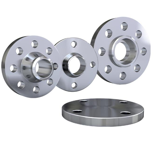
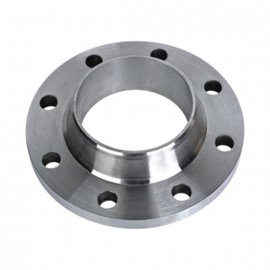
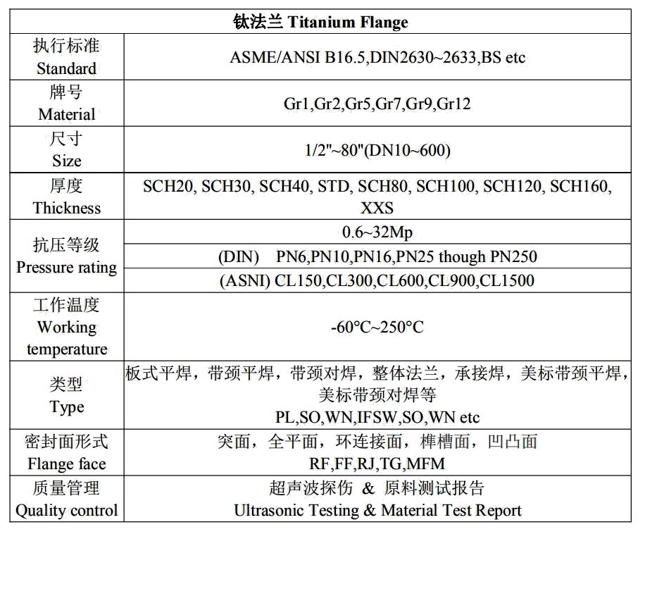
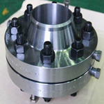
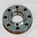
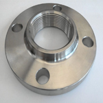
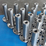
Titanium Flange
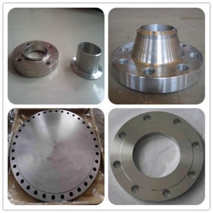
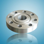
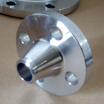
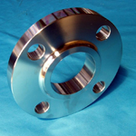
Types of Titanium Flange
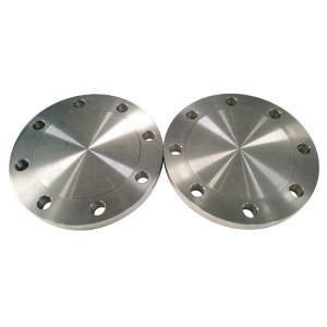
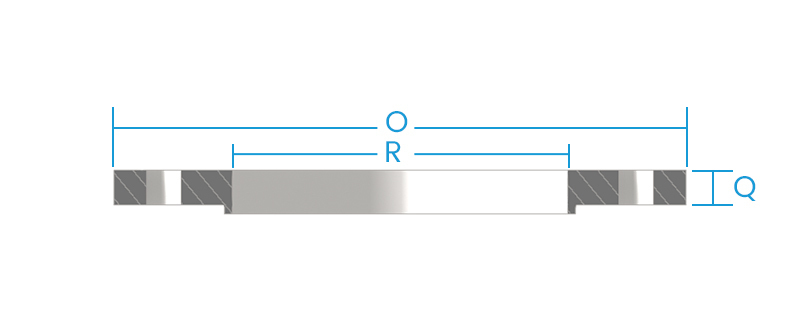
Blind Flanges
|
NOMINAL |
OUTSIDE |
THICKNESS |
DIA. OF |
NUMBER OF |
DIA. OF |
DIA. OF |
|
O |
Q** |
R |
||||
|
1/2 |
3-1/2 |
7/16 |
1-3/8 |
4 |
1/2 |
2-3/8 |
|
3/4 |
3-7/8 |
1/2 |
1-11/16 |
4 |
1/2 |
2-3/4 |
|
1 |
4-1/4 |
9/16 |
2 |
4 |
1/2 |
3-1/8 |
|
1-1/4 |
4-5/8 |
5/8 |
2-1/2 |
4 |
1/2 |
3-1/2 |
|
1-1/2 |
5 |
11/16 |
2-7/8 |
4 |
1/2 |
3-7/8 |
|
2 |
6 |
3/4 |
3-5/8 |
4 |
5/8 |
4-3/4 |
|
2-1/2 |
7 |
7/8 |
4-1/8 |
4 |
5/8 |
5-1/2 |
|
3 |
7-1/2 |
15/16 |
5 |
4 |
5/8 |
6 |
|
3-1/2 |
8-1/2 |
15/16 |
5-1/2 |
8 |
5/8 |
7 |
|
4 |
9 |
15/16 |
6-3/16 |
8 |
5/8 |
7-1/2 |
|
5 |
10 |
15/16 |
7-5/16 |
8 |
3/4 |
8-1/2 |
|
6 |
11 |
1 |
8-1/2 |
8 |
3/4 |
9-1/2 |
|
8 |
13-1/2 |
1-1/8 |
10-5/8 |
8 |
3/4 |
11-3/4 |
|
10 |
16 |
1-3/16 |
12-3/4 |
12 |
7/8 |
14-1/4 |
|
12 |
19 |
1-1/4 |
15 |
12 |
7/8 |
17 |
|
14 |
21 |
1-3/8 |
16-1/4 |
12 |
1 |
18-3/4 |
|
16 |
23-1/2 |
1-7/16 |
18-1/2 |
16 |
1 |
21-1/4 |
|
18 |
25 |
1-9/16 |
21 |
16 |
1-1/8 |
22-3/4 |
|
20 |
27-1/2 |
1-11/16 |
23 |
20 |
1-1/8 |
25 |
|
24 |
32 |
1-7/8 |
27-1/4 |
20 |
1-1/4 |
29-1/2 |
*When ordering specify nominal pipe size or “O” dimension in inches indicating which is being used, pressure rating of flange and part number.
** The 1/16″ raised face is included in Thickness “Q.”
+ Bolt holes are 1/8″ larger than bolt diameters.
• These lengths include thickness of two nuts but not height of crown.
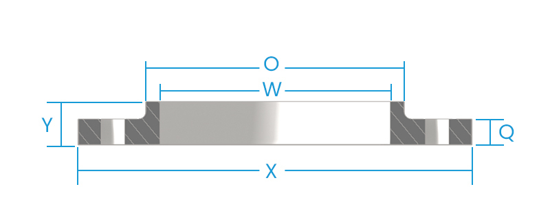
Slip-on Flanges
|
NOMINAL |
OUTSIDE |
THICKNESS |
DIA. OF |
DIA. OF HUB |
LENGTH |
DIA. OF BORE |
NUMBER OF |
DIA. OF |
DIA. OF |
|
O |
Q** |
R |
X |
Y** |
W |
||||
|
1/2 |
3-1/2 |
7/16 |
1-3/8 |
1-3/16 |
5/8 |
.88 |
4 |
1/2 |
2-3/8 |
|
3/4 |
3-7/8 |
1/2 |
1-11/16 |
1-1/2 |
5/8 |
1.09 |
4 |
1/2 |
2-3/4 |
|
1 |
4-1/4 |
9/16 |
2 |
1-15/16 |
11/16 |
1.36 |
4 |
1/2 |
3-1/8 |
|
1-1/4 |
4-5/8 |
5/8 |
2-1/2 |
2-5/16 |
13/16 |
1.70 |
4 |
1/2 |
3-1/2 |
|
1-1/2 |
5 |
11/16 |
2-7/8 |
2-9/16 |
7/8 |
1.95 |
4 |
1/2 |
3-7/8 |
|
2 |
6 |
3/4 |
3-5/8 |
3-1/16 |
1 |
2.44 |
4 |
5/8 |
4-3/4 |
|
2-1/2 |
7 |
7/8 |
4-1/8 |
3-9/16 |
1-1/8 |
2.94 |
4 |
5/8 |
5-1/2 |
|
3 |
7-1/2 |
15/16 |
5 |
4-1/4 |
1-3/16 |
3.57 |
4 |
5/8 |
6 |
|
3-1/2 |
8-1/2 |
15/16 |
5-1/2 |
4-13/16 |
1-1/4 |
4.07 |
8 |
5/8 |
7 |
|
4 |
9 |
15/16 |
6-3/16 |
5-5/16 |
1-5/16 |
4.57 |
8 |
5/8 |
7-1/2 |
|
5 |
10 |
15/16 |
7-5/16 |
6-7/16 |
1-7/16 |
5.66 |
8 |
3/4 |
8-1/2 |
|
6 |
11 |
1 |
8-1/2 |
7-9/16 |
1-9/16 |
6.72 |
8 |
3/4 |
9-1/2 |
|
8 |
13-1/2 |
1-1/8 |
10-5/8 |
9-11/16 |
1-3/4 |
8.72 |
8 |
3/4 |
11-3/4 |
|
10 |
16 |
1-3/16 |
12-3/4 |
12 |
1-15/16 |
10.88 |
12 |
7/8 |
14-1/4 |
|
12 |
19 |
1-1/4 |
15 |
14-3/8 |
2-3/16 |
12.88 |
12 |
7/8 |
17 |
|
14 |
21 |
1-3/8 |
16-1/4 |
15-3/4 |
2-1/4 |
14.14 |
12 |
1 |
18-3/4 |
|
16 |
23-1/2 |
1-7/16 |
18-1/2 |
18 |
2-1/2 |
16.16 |
16 |
1 |
21-1/4 |
|
18 |
25 |
1-9/16 |
21 |
19-7/8 |
2-11/16 |
18.18 |
16 |
1-1/8 |
22-3/4 |
|
20 |
27-1/2 |
1-11/16 |
23 |
22 |
2-7/8 |
20.20 |
20 |
1-1/8 |
25 |
|
24 |
32 |
1-7/8 |
27-1/4 |
26-1/8 |
3-1/4 |
24.25 |
20 |
1-1/4 |
29-1/2 |
** The 1/16″ raised face is included in Thickness “Q” and Length “Y.”
+ Bolt holes are 1/8″ larger than bolt diameters.
• These lengths include thickness of two nuts but not height of crown.
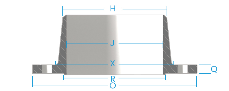
Weld Neck Flange
|
NOMINAL |
OUTSIDE |
THICKNESS |
DIA. OF |
DIA. OF |
MIN. DIA. OF HUB AT POINT OF WELDING |
LENGTH THRU HUB |
DIA. OF BORE |
NUMBER OF |
DIA. OF |
DIA. OF |
|
O |
Q** |
R |
X |
H |
Y** |
J ♢ |
||||
|
1/2 |
3-1/2 |
7/16 |
1-3/8 |
1-3/16 |
0.84 |
1-7/8 |
0.62 |
4 |
1/2 |
2-3/8 |
|
3/4 |
3-7/8 |
1/2 |
1-11/16 |
1-1/2 |
1.05 |
2-1/16 |
0.82 |
4 |
1/2 |
2-3/4 |
|
1 |
4-1/4 |
9/16 |
2 |
1-15/16 |
1.32 |
2-3/16 |
1.05 |
4 |
1/2 |
3-1/8 |
|
1-1/4 |
4-5/8 |
5/8 |
2-1/2 |
2-5/16 |
1.66 |
2-1/4 |
1.38 |
4 |
1/2 |
3-1/2 |
|
1-1/2 |
5 |
11/16 |
2-7/8 |
2-9/16 |
1.90 |
2-7/16 |
1.61 |
4 |
1/2 |
3-7/8 |
|
2 |
6 |
3/4 |
3-5/8 |
3-1/16 |
2.38 |
2-1/2 |
2.07 |
4 |
5/8 |
4-3/4 |
|
2-1/2 |
7 |
7/8 |
4-1/8 |
3-9/16 |
2.88 |
2-3/4 |
2.47 |
4 |
5/8 |
5-1/2 |
|
3 |
7-1/2 |
15/16 |
5 |
4-1/4 |
3.50 |
2-3/4 |
3.07 |
4 |
5/8 |
6 |
|
3-1/2 |
8-1/2 |
15/16 |
5-1/2 |
4-13/16 |
4.00 |
2-13/16 |
3.55 |
8 |
5/8 |
7 |
|
4 |
9 |
15/16 |
6-3/16 |
5-5/16 |
4.50 |
3 |
4.03 |
8 |
5/8 |
7-1/2 |
|
5 |
10 |
15/16 |
7-5/16 |
6-7/16 |
5.56 |
3-1/2 |
5.05 |
8 |
3/4 |
8-1/2 |
|
6 |
11 |
1 |
8-1/2 |
7-9/16 |
6.63 |
3-1/2 |
6.07 |
8 |
3/4 |
9-1/2 |
|
8 |
13-1/2 |
1-1/8 |
10-5/8 |
9-11/16 |
8.63 |
4 |
7.98 |
8 |
3/4 |
11-3/4 |
|
10 |
16 |
1-3/16 |
12-3/4 |
12 |
10.75 |
4 |
10.02 |
12 |
7/8 |
14-1/4 |
|
12 |
19 |
1-1/4 |
15 |
14-3/8 |
12.75 |
4-1/2 |
12.00 |
12 |
7/8 |
17 |
|
14 |
21 |
1-3/8 |
16-1/4 |
15-3/4 |
14.00 |
5 |
13.25 |
12 |
1 |
18-3/4 |
|
16 |
23-1/2 |
1-7/16 |
18-1/2 |
18 |
16.00 |
5 |
15.25 |
16 |
1 |
21-1/4 |
|
18 |
25 |
1-9/16 |
21 |
19-7/8 |
18.00 |
5-1/2 |
17.25 |
16 |
1-1/8 |
22-3/4 |
|
20 |
27-1/2 |
1-11/16 |
23 |
22 |
20.00 |
5-11/16 |
19.25 |
20 |
1-1/8 |
25 |
|
24 |
32 |
1-7/8 |
27-1/4 |
26-1/8 |
24.00 |
6 |
23.25 |
20 |
1-1/4 |
29-1/2 |
** The 1/16″ raised face is included in Thickness “Q” and Length “Y.”
+ Bolt holes are 1/8″ larger than bolt diameters.
• These lengths include thickness of two nuts but not height of crown.
♢ Unless otherwise ordered, flanges are bored to these dimensions which correspond to the I.D. of Standard Weight pipe as listed in American Standard B36.10.
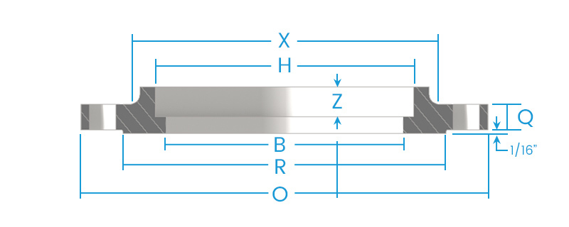
Socket Weld Flange
|
NOMINAL |
OUTSIDE |
THICKNESS |
DIA. OF |
DIA. OF HUB |
LENGTH |
DIA. OF |
DIA. OF |
DEPTH OF |
|
O |
Q** |
R |
X |
Y** |
B |
A |
Z |
|
|
1/4 |
3-1/2 |
7/16 |
1-3/8 |
1-3/16 |
5/8 |
0.364 |
0.580 |
3/8 |
|
3/8 |
3-1/2 |
7/16 |
1-3/8 |
1-3/16 |
5/8 |
0.493 |
0.715 |
3/8 |
|
1/2 |
3-1/2 |
7/16 |
1-3/8 |
1-3/16 |
5/8 |
0.622 |
0.88 |
3/8 |
|
3/4 |
3-7/8 |
1/2 |
1-11/16 |
1-1/2 |
5/8 |
0.824 |
1.09 |
7/16 |
|
1 |
4-1/4 |
9/16 |
2 |
1-15/16 |
1-1/16 |
1.049 |
1.36 |
1/2 |
|
1-1/4 |
4-5/8 |
5/8 |
2-1/2 |
2-5/16 |
1-3/16 |
1.380 |
1.70 |
9/16 |
|
1-1/2 |
5 |
11/16 |
2-7/8 |
2-9/16 |
7/8 |
1.610 |
1.95 |
5/8 |
|
2 |
6 |
3/4 |
3-5/8 |
3-1/16 |
1 |
2.067 |
2.44 |
11/16 |
|
2-1/2 |
7 |
7/8 |
4-1/8 |
3-9/16 |
1-1/8 |
2.469 |
2.94 |
3/4 |
|
3 |
7-1/2 |
15/16 |
5 |
4-1/4 |
1-3/16 |
3.068 |
3.57 |
13/16 |
|
3-1/2 |
8-1/2 |
15/16 |
5-1/2 |
4-13/16 |
1-1/4 |
3.548 |
4.07 |
7/8 |
|
4 |
9 |
15/16 |
6-3/16 |
5-5/16 |
1-5/16 |
4.026 |
4.56 |
15/16 |
|
5 |
10 |
15/16 |
7-5/16 |
6-7/16 |
1-7/16 |
5.047 |
5.66 |
15/16 |
|
6 |
11 |
1 |
8-1/2 |
7-9/16 |
1-9/16 |
6.065 |
6.72 |
1-1/16 |
|
8 |
13-1/2 |
1-1/8 |
10-5/8 |
9-11/16 |
1-3/4 |
7.981 |
8.72 |
1-1/4 |
|
10 |
16 |
1-3/16 |
12-3/4 |
12 |
1-15/16 |
10.020 |
10.88 |
1-5/16 |
|
12 |
19 |
1-1/4 |
15 |
14-3/8 |
2-3/16 |
12.000 |
12.88 |
1-9/16 |
|
14 |
21 |
1-3/8 |
16-1/4 |
15-3/4 |
2-1/4 |
13.250 |
14.19 |
1-5/8 |
|
16 |
23-1/2 |
1-7/16 |
18-1/2 |
18 |
2-1/2 |
15.250 |
16.19 |
1-3/4 |
|
18 |
25 |
1-9/16 |
21 |
19-7/8 |
2-11/16 |
17.250 |
18.19 |
1-15/16 |
|
20 |
27-1/2 |
1-11/16 |
23 |
22 |
2-7/8 |
19.250 |
20.19 |
2-1/8 |
|
24 |
32 |
1-7/8 |
27-1/4 |
26-1/8 |
3-1/4 |
23.250 |
24.19 |
2-1/2 |
*Sizes 1/2″ through 3″ are included in ASA B16/5-1953. Dimensions for all other sizes except for the bore dimension are the same as ASA Slip-on flanges.
** The 1/16″ raised face is included in Thickness “Q” and Length “Y.” Flanges are drilled the same as ASA 150-lb. flanges.
For other titanium flange types and sizes, please contact us
| ASME/ANSI B 16.5 | Welding Neck Flange, Slip on Flange, Blind Flange, High Hub Blind Flange, Socket Weld Flange, Lap Joint Flange, Threaded Flange, Ring Type Joint Flange |
| PRESSURE CLASS | 150, 300, 400, 600, 900, 1500, 2500 |
| ASME/ANSI B 16.47 | Welding Neck Flange, Blind Flange [Series A & B] |
| PRESSURE CLASS | 75, 150, 300, 400, 600, 900 |
| ASME/ANSI B 16.36 | Welding Neck Flange, Slip on Flange, Threaded Flange |
| PRESSURE CLASS | 300, 400, 600, 900, 1500, 2500 |
| BS 4504 SEC 3.1 | Welding Neck Flange, Hubbed Slip on Flange, Hubbed Threaded Flange, Lapped Pipe End Flange, Plate Flange, Loose Plate Flange, Loose Plate With Weld Neck Flange, Blank Flange |
| PRESSURE CLASS | PN 2.5 TO PN 40 |
| BS 4504[PART 1] | Welding Neck Flange, Hubbed Slip-On Hubbed Threaded, Plate Flange, Loose Plate With Weld On Plate Collar, Blank Flange |
| PRESSURE CLASS | PN 2.5 TO PN 400 |
| BS 1560 BOSS | Welding Neck Flange, Socket Welding Flange, Slip-On Flange, Blind Flange, Screwed Boss Flange, Lapped Flange |
| PRESSURE CLASS | 150, 300, 400, 600, 900, 1500, 2500 |
| BS10 | Welding Neck Flange, Plate Slip-On Flange, Screwed Boss Flange, Slip-On Boss Flange, Blind Flange |
| TABLE | D, E, F, H |
| DIN FLANGES | DIN 2527, 2566, 2573, 2576, 2641,2642, 2655, 2656, 2627, 2628, 2629, 2631, 2632, 2633, 2634, 2635, 2636, 2637,2638, 2673 |
| PRESSURE CLASS | PN 6 TO PN 100 |
Chemical composition
|
Grade |
Chemical composition, weight percent (%) |
||||||||||||
|
C (≤) |
O (≤) |
N (≤) |
H (≤) |
Fe (≤) |
Al |
V |
Pd |
Ru |
Ni |
Mo |
Other Elements Max. each |
Other Elements Max. total |
|
|
Gr1 |
0.08 |
0.18 |
0.03 |
0.015 |
0.20 |
— |
— |
— |
— |
— |
— |
0.1 |
0.4 |
|
Gr2 |
0.08 |
0.25 |
0.03 |
0.015 |
0.30 |
— |
— |
— |
— |
— |
— |
0.1 |
0.4 |
|
Gr4 |
0.08 |
0.25 |
0.03 |
0.015 |
0.30 |
— |
— |
— |
— |
— |
— |
0.1 |
0.4 |
|
Gr5 |
0.08 |
0.20 |
0.05 |
0.015 |
0.40 |
5.5~6.75 |
3.5~4.5 |
— |
— |
— |
— |
0.1 |
0.4 |
|
Gr7 |
0.08 |
0.25 |
0.03 |
0.015 |
0.30 |
— |
— |
0.12~0.25 |
— |
0.12~0.25 |
— |
0.1 |
0.4 |
|
Gr9 |
0.08 |
0.15 |
0.03 |
0.015 |
0.25 |
2.5~3.5 |
2.0~3.0 |
— |
— |
— |
— |
0.1 |
0.4 |
|
Gr11 |
0.08 |
0.18 |
0.03 |
0.15 |
0.2 |
— |
— |
0.12~0.25 |
— |
— |
— |
0.1 |
0.4 |
|
Gr12 |
0.08 |
0.25 |
0.03 |
0.15 |
0.3 |
— |
— |
— |
— |
0.6~0.9 |
0.2~0.4 |
0.1 |
0.4 |
|
Gr16 |
0.08 |
0.25 |
0.03 |
0.15 |
0.3 |
— |
— |
0.04~0.08 |
— |
— |
— |
0.1 |
0.4 |
|
Gr23 |
0.08 |
0.13 |
0.03 |
0.125 |
0.25 |
5.5~6.5 |
3.5~4.5 |
— |
— |
— |
— |
0.1 |
0.1 |

