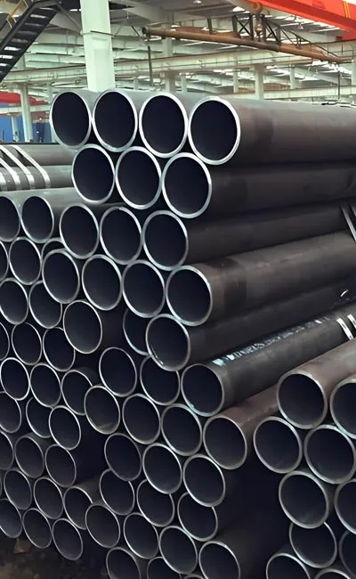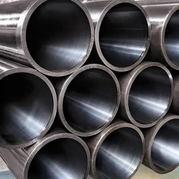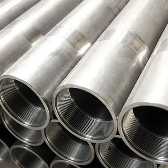

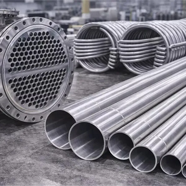
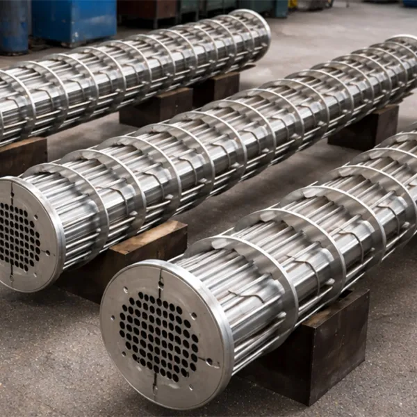
Heat Exchanger Steel Pipe, often referred to as heat exchanger tubing or condenser tubes, serves as the critical component in thermal transfer systems across various industries. These pipes are engineered to facilitate the efficient exchange of heat between two fluids (liquid or gas) without mixing them. Whether acting as a conduit for high-pressure steam or a medium for cooling water, the quality of the heat exchanger pipe directly impacts the energy efficiency and operational safety of the entire system.
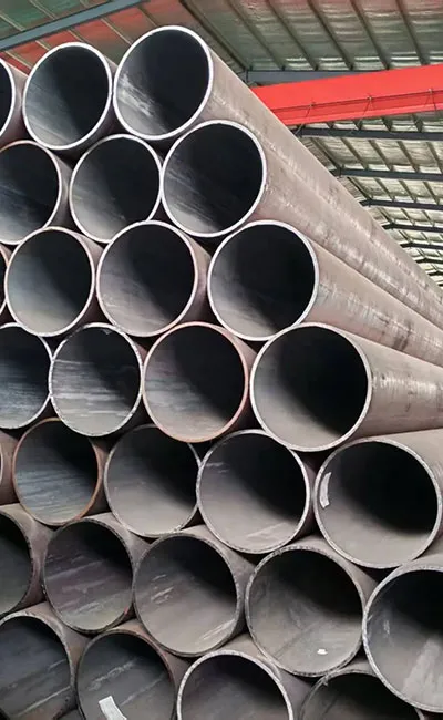
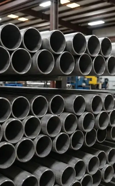
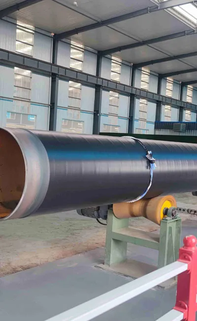
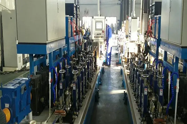
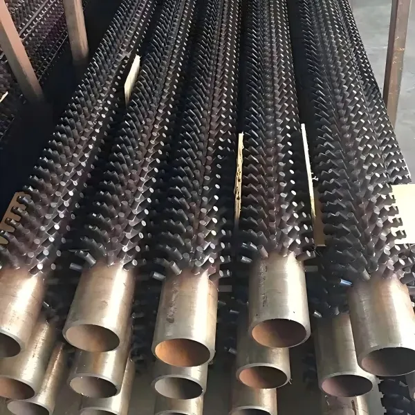
Our heat exchanger steel tubeare designed to withstand extreme operating conditions, including high pressure, elevated temperatures, and corrosive environments. The tubes are available in both seamless and welded configurations, utilizing materials ranging from low-carbon steel to high-grade stainless steel and alloy steel. Key characteristics include superior thermal conductivity, excellent surface finish to prevent fouling, and precise dimensional tolerances to ensure a perfect fit within tube sheets.
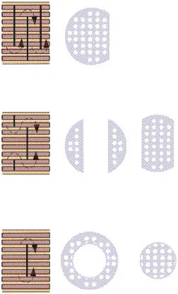
Common Types Of Heat Exchangers
Shell and tube heat exchangers:These are the most common types of heat exchangers used in commercial HVAC systems. They consist of a series of tubes enclosed in a shell. The hot fluid flows through the tubes while the cold fluid circulates the tubes within the shell, allowing for efficient heat exchanger.
Plate heat exchangers:Plate heat exchangers use a stack of metal plates with alternating raised and depressed areas. The hot and cold fluids flow through separate channels created by the gaps between the plates, maximizing heat transfer due to the large surface area.
Air-to-air heat exchangers: Also known as heat recovery units, these heat exchangers transfer heat between the extract and supply air streams. They remove heat from stale air and transfer it to fresh air, reducing energy consumption by pre-conditioning the incoming air.
How Many Types of Shell and Tube Heat Exchanger?
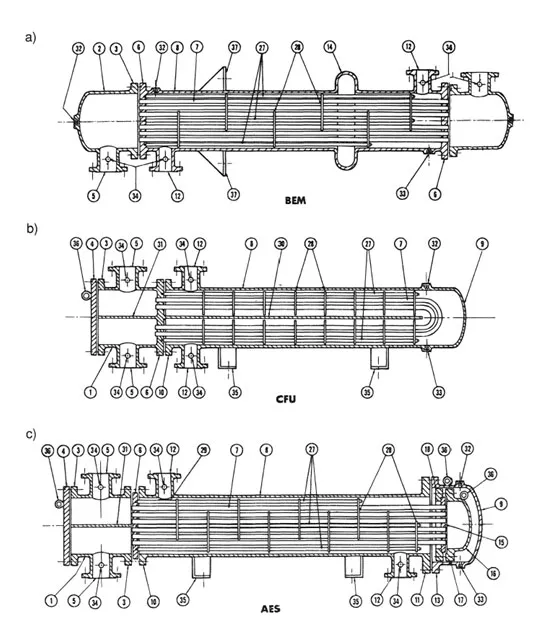
Essentially, there are three main types of shell and tube heat exchangers that are commonly used:
1. Fixed Tube Sheet Exchanger (L, M, and N Type Rear Headers)
In this design, the tube sheet is welded to the shell, resulting in a simple and economical construction. While the tube bores can be cleaned mechanically or chemically, the outside surfaces of the tubes are generally inaccessible except for chemical cleaning. Expansion bellows may be necessary to accommodate large temperature differences between the shell and tube materials, but they can be a source of weakness and failure.
2. U-Tube Exchangers
In a U-Tube exchanger, the front header types may vary, and the rear header is typically an M-Type. U-tubes allow for unlimited thermal expansion, and the tube bundle can be removed for cleaning. However, internal cleaning of the tubes by mechanical means is difficult, making this type suitable only for applications where the tube side fluids are clean.
3. Floating Head Exchanger (P, S, T, and W Type Rear Headers)
In this type of exchanger, the tubesheet at the rear header end is not welded to the shell but allowed to move or float. The tubesheet at the front header end is of a larger diameter than the shell and is sealed similarly to the fixed tubesheet design.
Thermal expansion can be accommodated, and the tube bundle can be removed for cleaning. The S-Type Rear Head is the most popular choice for the rear header. Floating head exchangers are suitable for high temperatures and pressures but are generally more expensive compared to fixed tubesheet exchangers.
Key Applications:
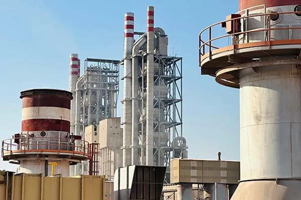
• Power Generation: Used extensively in surface condensers, high-pressure heaters, and low-pressure heaters in thermal and nuclear power plants.
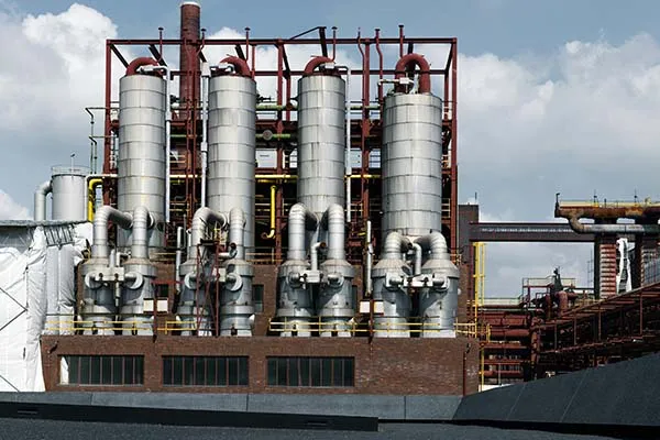
• Petrochemical Industry: Essential for shell-and-tube heat exchangers, crude oil coolers, and process heaters where corrosion resistance is vital.
• HVAC & Refrigeration: Utilized in central air conditioning systems, evaporators, and chillers for commercial buildings.
• Boiler Systems: Serving as boiler tubes that transfer heat from combustion gases to water to generate steam.
• Desalination Plants: Employed in multi-stage flash distillation units, requiring high resistance to seawater corrosion.
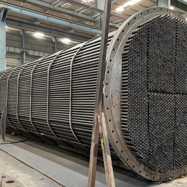
The components of a shell and tube heat exchanger can be broken down into the following parts:
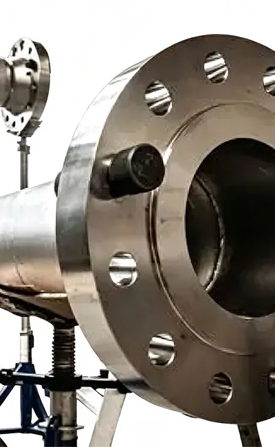
1. Shell
The shell is the heat exchanger’s outermost part which holds the tube bundle. It is commonly a cylindrical container constructed from steel or other appropriate substances
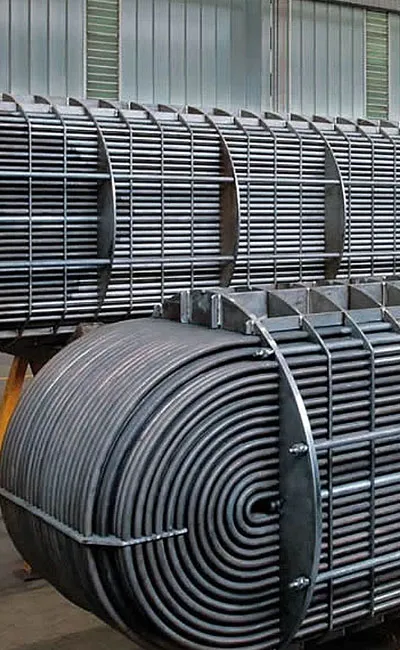
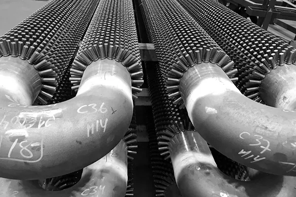
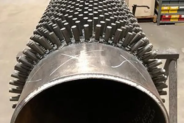
2. Tubes or Tube Bundle
A collection of parallel tubes running along the length of the shell makes up the tube bundle. Depending on the specific use, the tubes can be composed of different materials, such as stainless steel, copper, or titanium. The diameter and thickness of the tubes are also important design parameters.
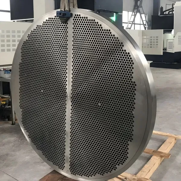
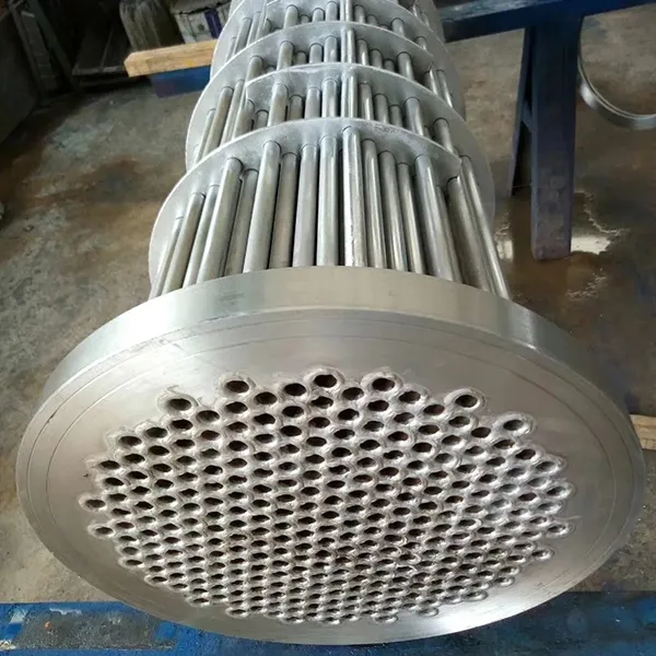
3. Tube Sheets
Tube sheets are sturdy sheets that act as a barrier between the tube bundle and the shell. They are commonly constructed using steel and are fused to the shell to ensure a firm and leak-free closure. The tubes are inserted through holes in the tube sheets and are either expanded or welded in position.
4. Baffles
Baffles are plates or rods that are placed inside the shell to regulate the movement of fluid around the tube bundle. These can be either longitudinal or transverse in orientation and are intended to enhance the effectiveness of heat transfer.
5. Inlet and Outlet Nozzles
The inlet and outlet nozzles serve as the entry and exit points for fluids in the heat exchanger. These connections are usually placed at opposite ends of the shell and are attached to the tubes and the shell using flanges or other types of fittings.
6. Expansion Joints
Expansion joints are flexible connectors that accommodate the tube bundle’s thermal expansion and contraction. Usually situated at the inlet and outlet of the heat exchanger, these joints are constructed using metal bellows or other flexible materials.
7. Support Structures
Support structures hold heat exchangers in position, ensuring a stable foundation. Support structures can be either temporary or permanent and may be made of steel or other materials.
Shell and tube geometric terminology
|
1 |
Stationary (Front) Head—Channel |
20 |
Slip-on Backing Flange |
|
2 |
Stationary (Front) Head—Bonnet |
21 |
Floating Tubesheet Skirt |
|
3 |
Stationary (Front) Head Flange |
22 |
Floating Tubesheet Skirt |
|
4 |
Channel Cover |
23 |
Packing Box Flange |
|
5 |
Stationary Head Nozzle |
24 |
Packing |
|
6 |
Stationary Tubesheet |
25 |
Packing Follower Ring |
|
7 |
Tubes |
26 |
Lantern Ring |
|
8 |
Shell |
27 |
Tie Rods and Spacers |
|
9 |
Shell Cover |
28 |
Transverse Baffles or Support Plates |
|
10 |
Shell Flange—Stationary Head End |
29 |
Impingement Baffle or Plate |
|
11 |
Shell Flange—Rear Head End |
30 |
Longitudinal Baffle |
|
12 |
Shell Nozzle |
31 |
Pass Partition |
|
13 |
Shell Cover Flange |
32 |
Vent Connection |
|
14 |
Expansion Joint |
33 |
Drain Connection |
|
15 |
Floating Tubesheet |
34 |
Instrument Connection |
|
16 |
Floating Head Cover |
35 |
Support Saddle |
|
17 |
Floating Head Flange |
36 |
Lifting Lug |
|
18 |
Floating Head Backing Device |
37 |
Support Bracket |
Tube diameter layout and pitch
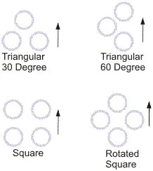
Tubes may range in diameter from 12.7 mm (0.5 in) to 50.8 mm (2 in), but 19.05 mm (0.75 in) and 25.4 mm (1 in) are the most common sizes. The tubes are laid out in triangular or square patterns in the tube sheets.
Baffle types
Baffles are installed on the shell side to give a higher heat-transfer rate due to increased turbulence and to support the tubes thus reducing the chance of damage due to vibration. There are a number of different baffle types, which support the tubes and promote flow across the tubes.
Single Segmental (this is the most common),
Double Segmental (this is used to obtain a lower shellside velocity and pressure drop),
Disc and Doughnut.
The center-to-center distance between baffles is called the baffle-pitch and this can be adjusted to vary the crossflow velocity. In practice the baffle pitch is not normally greater than a distance equal to the inside diameter of the shell or closer than a distance equal to one-fifth the diameter or 50.8 mm (2 in) whichever is greater. In order to allow the fluid to flow backwards and forwards across the tubes part of the baffle is cut away. The height of this part is referred to as the baffle-cut and is measured as a percentage of the shell diameter, e.g., 25 per cent baffle-cut. The size of the baffle-cut (or baffle window) needs to be considered along with the baffle pitch. It is normal to size the baffle-cut and baffle pitch to approximately equalize the velocities through the window and in crossflow, respectively.
The mechanical design of a shell and tube heat exchanger provides information on items such as shell thickness, flange thickness, etc. These are calculated using a pressure vessel design code such as the Boiler and Pressure Vessel code from ASME (American Society of Mechanical Engineers) and the British Master Pressure Vessel Standard, BS 5500. ASME is the most commonly used code for heat exchangers and is in 11 sections. Section VIII (Confined Pressure Vessels) of the code is the most applicable to heat exchangers but Sections II—Materials and Section V—Non Destructive Testing are also relevant.
Both ASME and BS5500 are widely used and accepted throughout the world but some countries insist that their own national codes are used. In order to try and simplify this the International Standards Organization is now attempting to develop a new internationally recognized code but it is likely to be a some time before this is accepted.
Mechanical Properties Specification Table
|
Standard |
Grade |
Tensile Strength (min MPa) |
Yield Strength (min MPa) |
|
Elongation (min %) |
Hardness (max HBW) |
|
ASTM A179 |
A179 |
≥ 325 |
≥ 180 |
|
≥ 35 |
163 |
|
ASTM A213 |
T11 |
≥ 415 |
≥ 205 |
|
≥ 30 |
163 |
|
ASTM A213 |
T22 |
≥ 415 |
≥ 205 |
|
≥ 30 |
163 |
|
ASTM A213 |
T91 |
≥ 585 |
≥ 415 |
|
≥ 20 |
250 |
|
ASTM A213 |
TP304 |
≥ 515 |
≥ 205 |
|
≥ 35 |
192 |
|
ASTM A213 |
TP316L |
≥ 485 |
≥ 170 |
|
≥ 35 |
192 |
|
DIN 17175 |
St35.8 |
360–480 |
≥ 235 |
|
≥ 25 |
— |
|
DIN 17175 |
13CrMo4-4 |
440–590 |
≥ 290 |
|
≥ 20 |
— |
A: ASTM A179 covers seamless cold-drawn low-carbon steel tubes for heat exchangers and condensers, suitable for service up to ~400°C. ASTM A213 covers seamless ferritic and austenitic alloy-steel tubes for boilers, superheaters, and heat exchangers, suitable for service up to 650°C (T91) or higher for austenitic grades. A179 is more economical for lower-temperature applications, while A213 offers superior creep strength and corrosion resistance for high-temperature and high-pressure service.
A: Seamless tubes have no weld seam, offering uniform structure and superior performance in high-pressure, high-temperature, and cyclic service conditions. Welded tubes are made by forming and welding a strip, offering tighter dimensional tolerances (especially wall thickness uniformity), smoother internal surfaces, and significantly lower cost (20–30% less). For most moderate-pressure heat exchanger applications, modern welded tubes perform equally well and are often the preferred choice for cost-sensitive projects. For critical high-pressure steam service (e.g., superheaters), seamless tubes are typically specified.
A: Grade A179 (carbon steel): up to ~400°C. Grade T11 (1.25Cr-0.5Mo): up to ~538°C. Grade T22 (2.25Cr-1Mo): up to ~565°C. Grade T91 (9Cr-1Mo-V): up to ~650°C. Austenitic stainless grades (TP304, TP316): up to ~750°C (creep strength limited above 650°C). For temperatures above 750°C, nickel-based alloys are recommended.
A: Straight tubes are the standard configuration for most shell-and-tube heat exchangers, with tubes fixed at both ends to tube sheets. U-bend tubes are bent into a U-shape, allowing the tube bundle to expand and contract freely without stressing the tube sheets, eliminating the need for an expansion joint. U-bend tubes are preferred for high-temperature differential applications.
A: EN 10204 Type 3.1 mill test certificates (MTC) with full traceability to heat number, including chemical analysis, mechanical properties, NDE results, and hydrostatic test records. Type 3.2 certificates with third-party verification (SGS, BV, TÜV) are also available. ASME Code stamping (SA179/SA213/SA249) can be provided for pressure vessel applications.
The components of a shell and tube heat exchanger can be broken down into the following parts:
1. Shell
The shell is the heat exchanger’s outermost part which holds the tube bundle. It is commonly a cylindrical container constructed from steel or other appropriate substances
2. Tubes or Tube Bundle
A collection of parallel tubes running along the length of the shell makes up the tube bundle. Depending on the specific use, the tubes can be composed of different materials, such as stainless steel, copper, or titanium. The diameter and thickness of the tubes are also important design parameters.
3. Tube Sheets
Tube sheets are sturdy sheets that act as a barrier between the tube bundle and the shell. They are commonly constructed using steel and are fused to the shell to ensure a firm and leak-free closure. The tubes are inserted through holes in the tube sheets and are either expanded or welded in position.
4. Baffles
Baffles are plates or rods that are placed inside the shell to regulate the movement of fluid around the tube bundle. These can be either longitudinal or transverse in orientation and are intended to enhance the effectiveness of heat transfer.
5. Inlet and Outlet Nozzles
The inlet and outlet nozzles serve as the entry and exit points for fluids in the heat exchanger. These connections are usually placed at opposite ends of the shell and are attached to the tubes and the shell using flanges or other types of fittings.
6. Expansion Joints
Expansion joints are flexible connectors that accommodate the tube bundle’s thermal expansion and contraction. Usually situated at the inlet and outlet of the heat exchanger, these joints are constructed using metal bellows or other flexible materials.
7. Support Structures
Support structures hold heat exchangers in position, ensuring a stable foundation. Support structures can be either temporary or permanent and may be made of steel or other materials.
Shell and tube geometric terminology
|
1 |
Stationary (Front) Head—Channel |
20 |
Slip-on Backing Flange |
|
2 |
Stationary (Front) Head—Bonnet |
21 |
Floating Tubesheet Skirt |
|
3 |
Stationary (Front) Head Flange |
22 |
Floating Tubesheet Skirt |
|
4 |
Channel Cover |
23 |
Packing Box Flange |
|
5 |
Stationary Head Nozzle |
24 |
Packing |
|
6 |
Stationary Tubesheet |
25 |
Packing Follower Ring |
|
7 |
Tubes |
26 |
Lantern Ring |
|
8 |
Shell |
27 |
Tie Rods and Spacers |
|
9 |
Shell Cover |
28 |
Transverse Baffles or Support Plates |
|
10 |
Shell Flange—Stationary Head End |
29 |
Impingement Baffle or Plate |
|
11 |
Shell Flange—Rear Head End |
30 |
Longitudinal Baffle |
|
12 |
Shell Nozzle |
31 |
Pass Partition |
|
13 |
Shell Cover Flange |
32 |
Vent Connection |
|
14 |
Expansion Joint |
33 |
Drain Connection |
|
15 |
Floating Tubesheet |
34 |
Instrument Connection |
|
16 |
Floating Head Cover |
35 |
Support Saddle |
|
17 |
Floating Head Flange |
36 |
Lifting Lug |
|
18 |
Floating Head Backing Device |
37 |
Support Bracket |
Tube diameter layout and pitch
Tubes may range in diameter from 12.7 mm (0.5 in) to 50.8 mm (2 in), but 19.05 mm (0.75 in) and 25.4 mm (1 in) are the most common sizes. The tubes are laid out in triangular or square patterns in the tube sheets.
Baffle types
Baffles are installed on the shell side to give a higher heat-transfer rate due to increased turbulence and to support the tubes thus reducing the chance of damage due to vibration. There are a number of different baffle types, which support the tubes and promote flow across the tubes.
Single Segmental (this is the most common),
Double Segmental (this is used to obtain a lower shellside velocity and pressure drop),
Disc and Doughnut.
The center-to-center distance between baffles is called the baffle-pitch and this can be adjusted to vary the crossflow velocity. In practice the baffle pitch is not normally greater than a distance equal to the inside diameter of the shell or closer than a distance equal to one-fifth the diameter or 50.8 mm (2 in) whichever is greater. In order to allow the fluid to flow backwards and forwards across the tubes part of the baffle is cut away. The height of this part is referred to as the baffle-cut and is measured as a percentage of the shell diameter, e.g., 25 per cent baffle-cut. The size of the baffle-cut (or baffle window) needs to be considered along with the baffle pitch. It is normal to size the baffle-cut and baffle pitch to approximately equalize the velocities through the window and in crossflow, respectively.
The mechanical design of a shell and tube heat exchanger provides information on items such as shell thickness, flange thickness, etc. These are calculated using a pressure vessel design code such as the Boiler and Pressure Vessel code from ASME (American Society of Mechanical Engineers) and the British Master Pressure Vessel Standard, BS 5500. ASME is the most commonly used code for heat exchangers and is in 11 sections. Section VIII (Confined Pressure Vessels) of the code is the most applicable to heat exchangers but Sections II—Materials and Section V—Non Destructive Testing are also relevant.
Both ASME and BS5500 are widely used and accepted throughout the world but some countries insist that their own national codes are used. In order to try and simplify this the International Standards Organization is now attempting to develop a new internationally recognized code but it is likely to be a some time before this is accepted.
Mechanical Properties Specification Table
|
Standard |
Grade |
Tensile Strength (min MPa) |
Yield Strength (min MPa) |
|
Elongation (min %) |
Hardness (max HBW) |
|
ASTM A179 |
A179 |
≥ 325 |
≥ 180 |
|
≥ 35 |
163 |
|
ASTM A213 |
T11 |
≥ 415 |
≥ 205 |
|
≥ 30 |
163 |
|
ASTM A213 |
T22 |
≥ 415 |
≥ 205 |
|
≥ 30 |
163 |
|
ASTM A213 |
T91 |
≥ 585 |
≥ 415 |
|
≥ 20 |
250 |
|
ASTM A213 |
TP304 |
≥ 515 |
≥ 205 |
|
≥ 35 |
192 |
|
ASTM A213 |
TP316L |
≥ 485 |
≥ 170 |
|
≥ 35 |
192 |
|
DIN 17175 |
St35.8 |
360–480 |
≥ 235 |
|
≥ 25 |
— |
|
DIN 17175 |
13CrMo4-4 |
440–590 |
≥ 290 |
|
≥ 20 |
— |
A: ASTM A179 covers seamless cold-drawn low-carbon steel tubes for heat exchangers and condensers, suitable for service up to ~400°C. ASTM A213 covers seamless ferritic and austenitic alloy-steel tubes for boilers, superheaters, and heat exchangers, suitable for service up to 650°C (T91) or higher for austenitic grades. A179 is more economical for lower-temperature applications, while A213 offers superior creep strength and corrosion resistance for high-temperature and high-pressure service.
A: Seamless tubes have no weld seam, offering uniform structure and superior performance in high-pressure, high-temperature, and cyclic service conditions. Welded tubes are made by forming and welding a strip, offering tighter dimensional tolerances (especially wall thickness uniformity), smoother internal surfaces, and significantly lower cost (20–30% less). For most moderate-pressure heat exchanger applications, modern welded tubes perform equally well and are often the preferred choice for cost-sensitive projects. For critical high-pressure steam service (e.g., superheaters), seamless tubes are typically specified.
A: Grade A179 (carbon steel): up to ~400°C. Grade T11 (1.25Cr-0.5Mo): up to ~538°C. Grade T22 (2.25Cr-1Mo): up to ~565°C. Grade T91 (9Cr-1Mo-V): up to ~650°C. Austenitic stainless grades (TP304, TP316): up to ~750°C (creep strength limited above 650°C). For temperatures above 750°C, nickel-based alloys are recommended.
A: Straight tubes are the standard configuration for most shell-and-tube heat exchangers, with tubes fixed at both ends to tube sheets. U-bend tubes are bent into a U-shape, allowing the tube bundle to expand and contract freely without stressing the tube sheets, eliminating the need for an expansion joint. U-bend tubes are preferred for high-temperature differential applications.
A: EN 10204 Type 3.1 mill test certificates (MTC) with full traceability to heat number, including chemical analysis, mechanical properties, NDE results, and hydrostatic test records. Type 3.2 certificates with third-party verification (SGS, BV, TÜV) are also available. ASME Code stamping (SA179/SA213/SA249) can be provided for pressure vessel applications.


 English
 Español
 русский язык
 Português