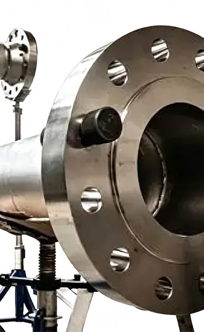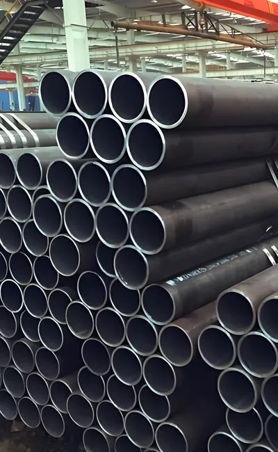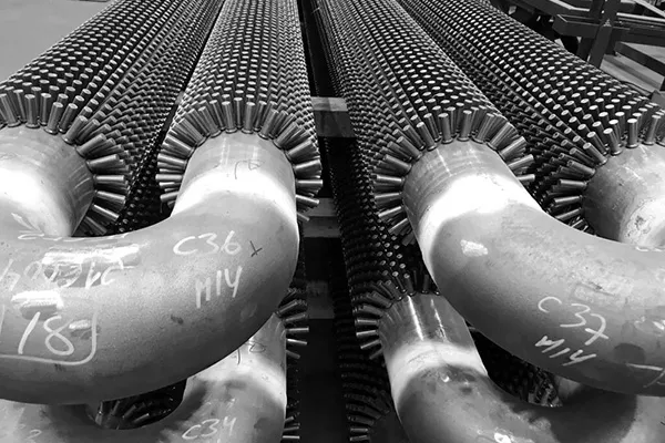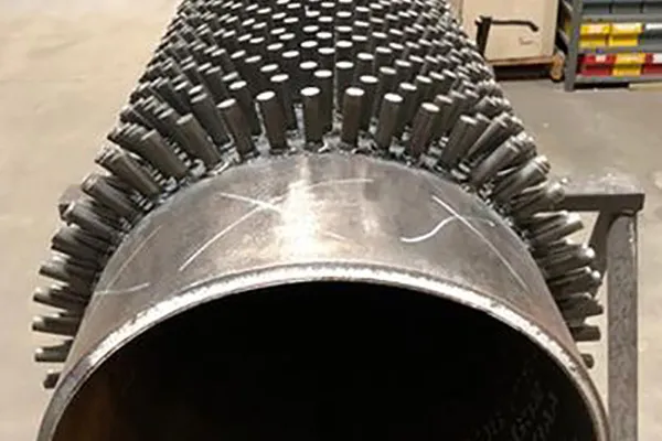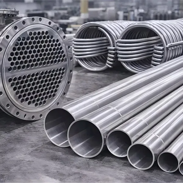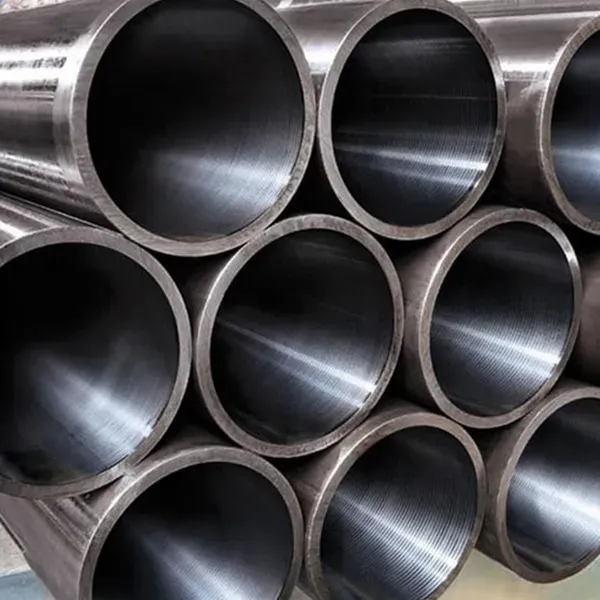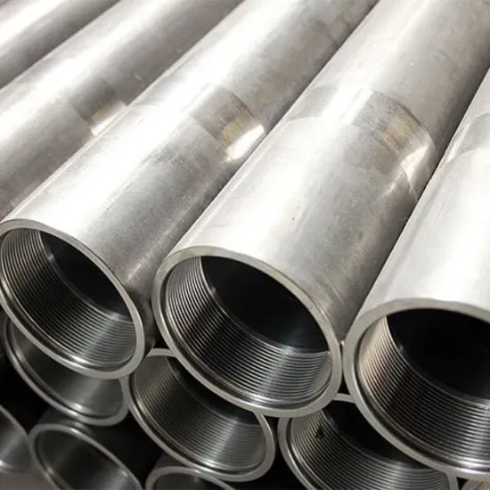

Heat Exchange Steel Pipe Fittings are the critical connective components that ensure the integrity and efficiency of thermal transfer systems. Unlike standard piping fittings, those designed for heat exchange applications must withstand extreme thermal cycling, high pressure, and often corrosive media while maintaining precise dimensional tolerances to facilitate smooth fluid dynamics. These fittings—including U-bends, elbows, tees, headers, and return bends—serve as the junction points that direct the flow of fluids within shell-and-tube heat exchangers, condensers, and boiler systems.
The primary function of a heat exchange fitting is to maximize thermal transfer efficiency while minimizing pressure drop and flow turbulence. For instance, the internal surface finish of these fittings is often polished to a specific roughness average to prevent fouling, scaling, or bacterial growth, which can severely impede heat transfer. Materials are selected based on the specific thermal conductivity and corrosion resistance required; common choices include high-grade stainless steels (304/316), duplex steels, nickel alloys (Inconel, Monel), and specialized carbon steels.
Key Applications:
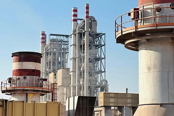
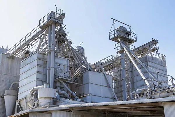
• Power Generation: Used in high-pressure feedwater heaters, surface condensers, and closed-loop cooling systems in thermal and nuclear power plants.
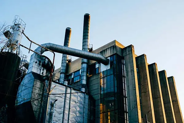
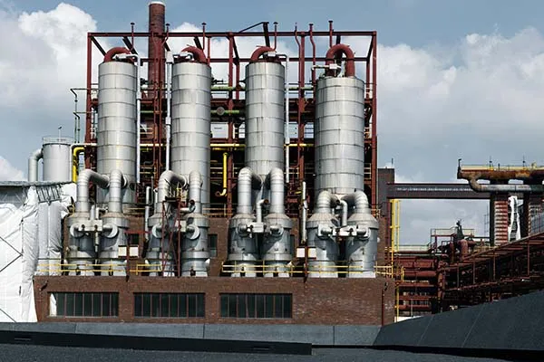
• Petrochemical & Refining: Essential for connecting tubes in shell-and-tube heat exchangers that process crude oil, natural gas, and chemical byproducts under high temperatures.
• HVAC & Refrigeration: Utilized in large-scale chiller systems and evaporators where precise flow direction is necessary for efficient cooling.
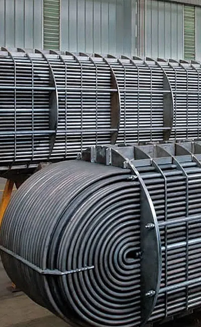
• Desalination Plants: Components like U-bends and return headers are used in multi-stage flash distillation units, requiring high resistance to seawater corrosion.
• Pharmaceutical Industry: Sanitary fittings with electropolished interiors are used in heat exchangers for processing sensitive fluids where hygiene is paramount.
The Heat Exchange Steel Pipe Fitting is manufactured to precise dimensional, material, and mechanical specifications. Below are detailed specification tables covering key parameters.
Dimensional Specification Table (Butt-Weld Fittings per ASME B16.9)
|
Fitting Type |
Nominal Pipe Size (NPS) |
OD Range (mm) |
Wall Thickness Schedule |
Dimensional Tolerances |
|
45° / 90° Elbow |
½″ – 48″ (DN15 – DN1200) |
21.3 – 1219 |
Sch 5S, 10S, 40S, 80S, 160, XXS |
OD: ±1.6 mm (≤4″); ±2.4 mm (>4″); End-to-end: ±2 mm |
|
Equal Tee |
½″ – 48″ |
21.3 – 1219 |
Sch 5S – XXS |
Center-to-end: ±2 mm (≤4″); ±3 mm (>4″) |
|
Reducing Tee |
½″ – 48″ (run) / ½″ – 24″ (branch) |
As above |
As above |
Branch center offset: ±3 mm |
|
Concentric / Eccentric Reducer |
½″ – 48″ |
21.3 – 1219 |
As above |
Length (end-to-end): ±2 mm (≤4″); ±4 mm (>4″) |
|
Cap |
½″ – 48″ |
21.3 – 1219 |
As above |
Length: ±3 mm |
|
Stub End (Lap Joint) |
½″ – 24″ |
21.3 – 610 |
Sch 5S – 80S |
Length (long pattern): +3/-0 mm |
Material Grade & Chemical Composition Table
|
Standard |
Grade |
UNS No. |
C (%) |
Mn (%) |
Si (%) |
Cr (%) |
Mo (%) |
Ni (%) |
Others |
|
ASTM A234 |
WPB |
K03006 |
≤0.30 |
0.29–1.06 |
≥0.10 |
— |
— |
— |
P≤0.05; S≤0.058 |
|
ASTM A234 |
WP11 Class 1 |
— |
0.05–0.15 |
0.30–0.60 |
0.50–1.00 |
1.00–1.50 |
0.44–0.65 |
— |
P≤0.03; S≤0.03 |
|
ASTM A234 |
WP22 Class 3 |
— |
0.05–0.15 |
0.30–0.60 |
≤0.50 |
1.90–2.60 |
0.87–1.13 |
— |
P≤0.03; S≤0.03 |
|
ASTM A234 |
WP91 |
K90901 |
0.08–0.12 |
0.30–0.60 |
0.20–0.50 |
8.00–9.50 |
0.85–1.05 |
≤0.40 |
V:0.18-0.25; Nb:0.06-0.10; N:0.03-0.07 |
|
ASTM A403 |
WP304 |
S30400 |
≤0.08 |
≤2.00 |
≤1.00 |
18.0–20.0 |
— |
8.0–11.0 |
P≤0.045; S≤0.030 |
|
ASTM A403 |
WP316L |
S31603 |
≤0.035 |
≤2.00 |
≤1.00 |
16.0–18.0 |
2.00–3.00 |
10.0–14.0 |
P≤0.045; S≤0.030 |
|
ASTM A420 |
WPL6 |
K03006 |
≤0.30 |
0.50–1.35 |
0.15–0.30 |
— |
— |
— |
Impact tested at -46°C |
Mechanical Properties & Heat Treatment Table
|
Grade |
Tensile Strength (min MPa) |
Yield Strength (min MPa) |
Elongation (min %) |
Hardness (max HBW) |
Required Heat Treatment |
|
WPB |
415 |
240 |
22 |
197 |
Normalized or stress relieved |
|
WP11 Class 1 |
415 |
205 |
20 |
163 |
Normalized & tempered |
|
WP22 Class 3 |
415 |
205 |
20 |
163 |
Normalized & tempered |
|
WP91 |
585 |
415 |
20 |
250 |
Normalized & tempered (austenitized at 1040-1080°C) |
|
WP304 |
515 |
205 |
35 |
192 |
Solution annealed |
|
WP316L |
485 |
170 |
35 |
192 |
Solution annealed |
|
WPL6 |
415 |
240 |
22 |
197 |
Normalized, or quenched & tempered |
The Heat Exchange Steel Pipe Fitting is manufactured and tested in compliance with a comprehensive range of international standards covering dimensional requirements, material specifications, and testing protocols. The tables below summarize the key applicable standards.
Primary Standards for Heat Exchange Steel Pipe Fittings
|
Standard |
Full Title |
Fitting Types Covered |
Material Scope |
Key Features |
|
ASME B16.9 |
Factory-Made Wrought Butt-Welding Fittings |
Elbows, tees, reducers, caps, lap joint stub ends |
Carbon, alloy, stainless steel |
Most widely used standard; covers NPS ½″–48″; 5 schedules; defines dimensional tolerances |
|
ASME B16.11 |
Forged Fittings, Socket-Welding and Threaded |
Socket-weld and threaded elbows, tees, couplings, caps, plugs, unions |
Carbon, alloy, stainless steel |
For NPS ½″–4″; Classes 3000, 6000, 9000 |
|
ASME B16.25 |
Butt-welding Ends |
Bevel dimensions for butt-weld fittings |
All materials |
Defines bevel angle (37.5°), root face (1.6 mm), and land |
|
ASTM A234 |
Piping Fittings of Wrought Carbon Steel and Alloy Steel for Moderate and High-Temperature Service |
Butt-weld, socket-weld, threaded fittings |
Carbon (WPB), alloy (WP1, WP5, WP9, WP11, WP22, WP91) |
Primary material standard for ferritic fittings |
|
ASTM A403 |
Wrought Austenitic Stainless Steel Piping Fittings |
Butt-weld, socket-weld, threaded fittings |
WP304, WP304L, WP316, WP316L, WP321, WP347 |
For stainless steel heat exchanger fittings |
|
ASTM A420 |
Piping Fittings of Wrought Carbon Steel and Alloy Steel for Low-Temperature Service |
Butt-weld, socket-weld, threaded fittings |
WPL6, WPL9 |
Impact tested at -46°C (WPL6) or -73°C (WPL9) |
|
ASTM A815 |
Wrought Ferritic, Ferritic/Austenitic, and Martensitic Stainless Steel Piping Fittings |
Butt-weld, socket-weld |
Duplex (S31803, S32205), super duplex |
For heat exchangers in corrosive / chloride service |
|
EN 10253 (Parts 1-4) |
Butt-welding pipe fittings (European standard) |
Elbows, tees, reducers, caps |
Non-alloy, alloy, stainless steel |
PED-compliant; CE marking available |
|
MSS SP-75 |
High-Test Wrought Butt-Welding Fittings |
Elbows, tees, reducers, caps |
High-strength carbon steel (Gr. 42, 52, 62, 70) |
For large-diameter, high-pressure gas/oil pipelines |
Dimensional Tolerances per ASME B16.9 (Selected Examples)
|
Fitting Type |
NPS Range |
Outside Diameter (at bevel) |
Wall Thickness |
Center-to-End Dimension |
Alignment / Angularity |
|
90° Elbow |
½″ – 2½″ |
±1.6 mm |
±12.5% |
±2 mm |
— |
|
90° Elbow |
3″ – 3½″ |
±1.6 mm |
±12.5% |
±2 mm |
— |
|
90° Elbow |
4″ |
±2.4 mm |
±12.5% |
±2 mm |
— |
|
90° Elbow |
5″ – 8″ |
±2.4 mm |
±12.5% |
±3 mm |
— |
|
90° Elbow |
10″ – 18″ |
±4 mm |
±12.5% |
±4 mm |
— |
|
90° Elbow |
20″ – 24″ |
±4 mm |
±12.5% |
±5 mm |
— |
|
Tee (branch run) |
All sizes |
As above |
As above |
±2 mm (≤4″); ±3 mm (5″-8″); ±4 mm (10″-18″); ±5 mm (≥20″) |
Branch offset ±3 mm max |
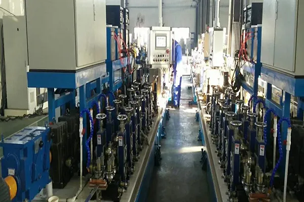
The manufacturing process of Heat Exchange Steel Pipe Fittings follows a controlled sequence to ensure dimensional accuracy, material integrity, and traceability. The most common method for butt-weld fittings is hot forming, while socket-weld and threaded fittings are typically forged.
Step 1–Raw Material Inspection: Steel plates, bars, or forgings are received with mill certificates. Chemical composition is verified via PMI (Positive Material Identification). For alloy and stainless grades, 100% PMI is performed.
Step 2–Cutting & Heating: The raw material is cut to calculated blank size (developed length based on final fitting dimensions). For hot forming, blanks are heated in a controlled atmosphere furnace to forging temperature (950–1200°C depending on material). Carbon steel: ~1050°C; stainless steel: ~1100°C; alloy steel: ~1150°C.
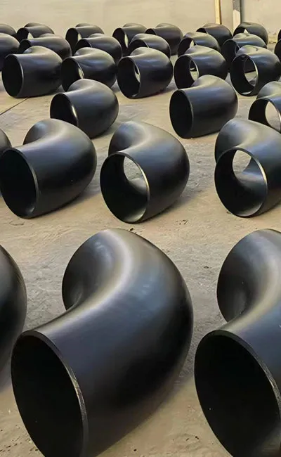
Step 3–Forming: Heated blanks are formed using hydraulic presses, mandrels, or expanders into the required fitting shape. Elbows are typically formed by bending straight pipe sections or by pressing two halves (seamless elbow). Tees are extruded or pressed from a pipe blank with a branch outlet. Reducers are swaged or pressed from pipe sections. Caps are stamped or pressed from plate.
Step 4–Heat Treatment: After forming, fittings undergo specified heat treatment to relieve forming stresses, refine grain structure, and achieve required mechanical properties. Carbon steel (WPB): normalize or stress relieve at 600–650°C. Alloy steel (WP11, WP22): normalize at 900–950°C, then temper at 650–750°C. Stainless steel (WP304/316L): solution anneal at 1040–1120°C, followed by rapid cooling (water quenching). For WP91, austenitizing at 1040–1080°C, air cool, then temper at 730–800°C.
Step 5–Machining & Beveling: Fittings are machined to final dimensions on CNC lathes or milling machines. Bevel ends are prepared per ASME B16.25 (37.5° ±2.5°bevel, 1.6 mm root face). Threads are cut for threaded fittings per ASME B1.20.1 (NPT).
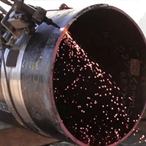
Step 6–Nondestructive Examination (NDE): 100% visual inspection. Radiographic testing (RT) is performed on a spot or 100% basis as required by customer or code. For alloy and stainless fittings, dye penetrant (PT) or magnetic particle (MT) is applied to detect surface cracks.
Step 7–Dimensional Inspection & Marking: Each fitting is measured for critical dimensions (OD, ID, wall thickness, center-to-end, bevel angle). Acceptable fittings are stamped or laser-marked with manufacturer, material grade, size, schedule, heat number, and standard (e.g.,“A234 WPB 4″Sch 40 ASME B16.9”).
Step 8–Surface Finishing & Packaging: Fittings are cleaned (shot blasting or pickling for stainless), and carbon steel fittings receive a rust-preventive coating. Finally, fittings are packed according to customer requirements.
Proper packing is essential to protect the precise geometry and surface finish of heat exchange fittings during transportation and storage.
• Surface Protection: For stainless steel and nickel alloy fittings, the surface is protected with plastic film or tape to prevent iron contamination and scratches. Carbon steel fittings are often coated with anti-rust oil and varnish.
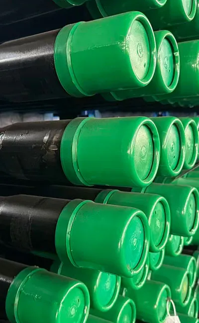
• End Protection: The beveled ends are fitted with plastic or wooden caps to prevent damage to the welding bevel, which is critical for achieving a high-quality weld on-site.
• Bundling & Crating:
• Small Fittings: Elbows and tees under 4 inches are bundled in strong wooden crates or plywood boxes, separated by layers of paper or foam to prevent friction.
• Large Fittings & U-Bends: Large diameter fittings and U-bend bundles are secured on wooden skids or in open-top crates. They are strapped down securely to prevent movement during transit.
• Desiccants: Silica gel packets or VCI (Vapor Corrosion Inhibitor) bags are placed inside the packaging to absorb moisture and prevent oxidation, especially for ocean freight.
• Marking: Each fitting is stenciled with the material grade, size, heat number, and standard (e.g., "ASTM A403 WP316L"). The outside of the crate is marked with the gross weight, dimensions, and handling instructions (e.g., "Fragile,""Keep Dry").
A: Carbon steel (ASTM A234 WPB) for moderate temperatures up to 425°C; alloy steel (A234 WP11, WP22, WP91) for high-temperature creep service up to 650°C; stainless steel (A403 WP304/316L) for corrosion resistance and high-temperature strength; low-temperature carbon steel (A420 WPL6) for cryogenic service down to -46°C; duplex stainless (A815) for chloride-rich environments.
A: Heat treatment (normalizing, tempering, or solution annealing) relieves residual stresses from forming, refines grain structure, and ensures the required mechanical properties (strength, toughness, hardness). For alloy fittings (WP11, WP22, WP91), proper heat treatment is essential to achieve creep resistance and prevent premature failure at high temperatures.
A: Standard tests include 100% visual inspection, dimensional verification, PMI (material composition), hardness testing, and optionally radiographic (RT), dye penetrant (PT), or ultrasonic (UT) testing depending on service requirements. For low-temperature service, impact testing (Charpy V-notch) is performed. Hydrostatic testing of the assembled fitting may also be required.
A: WP11 (1.25% Cr, 0.5% Mo) is suitable for service up to ~538°C, commonly used in superheater and reheater piping. WP22 (2.25% Cr, 1% Mo) offers higher creep strength and is suitable up to ~565°C, often used in main steam piping and feedwater heaters. Both require normalizing and tempering heat treatment.
A: Yes. When ordered with authorized ASME inspection, fittings can be stamped with the appropriate ASME symbol (e.g.,“U”for pressure vessels,“PP”for power piping) and supplied with certified documentation.
The Heat Exchange Steel Pipe Fitting is manufactured to precise dimensional, material, and mechanical specifications. Below are detailed specification tables covering key parameters.
Dimensional Specification Table (Butt-Weld Fittings per ASME B16.9)
|
Fitting Type |
Nominal Pipe Size (NPS) |
OD Range (mm) |
Wall Thickness Schedule |
Dimensional Tolerances |
|
45° / 90° Elbow |
½″ – 48″ (DN15 – DN1200) |
21.3 – 1219 |
Sch 5S, 10S, 40S, 80S, 160, XXS |
OD: ±1.6 mm (≤4″); ±2.4 mm (>4″); End-to-end: ±2 mm |
|
Equal Tee |
½″ – 48″ |
21.3 – 1219 |
Sch 5S – XXS |
Center-to-end: ±2 mm (≤4″); ±3 mm (>4″) |
|
Reducing Tee |
½″ – 48″ (run) / ½″ – 24″ (branch) |
As above |
As above |
Branch center offset: ±3 mm |
|
Concentric / Eccentric Reducer |
½″ – 48″ |
21.3 – 1219 |
As above |
Length (end-to-end): ±2 mm (≤4″); ±4 mm (>4″) |
|
Cap |
½″ – 48″ |
21.3 – 1219 |
As above |
Length: ±3 mm |
|
Stub End (Lap Joint) |
½″ – 24″ |
21.3 – 610 |
Sch 5S – 80S |
Length (long pattern): +3/-0 mm |
Material Grade & Chemical Composition Table
|
Standard |
Grade |
UNS No. |
C (%) |
Mn (%) |
Si (%) |
Cr (%) |
Mo (%) |
Ni (%) |
Others |
|
ASTM A234 |
WPB |
K03006 |
≤0.30 |
0.29–1.06 |
≥0.10 |
— |
— |
— |
P≤0.05; S≤0.058 |
|
ASTM A234 |
WP11 Class 1 |
— |
0.05–0.15 |
0.30–0.60 |
0.50–1.00 |
1.00–1.50 |
0.44–0.65 |
— |
P≤0.03; S≤0.03 |
|
ASTM A234 |
WP22 Class 3 |
— |
0.05–0.15 |
0.30–0.60 |
≤0.50 |
1.90–2.60 |
0.87–1.13 |
— |
P≤0.03; S≤0.03 |
|
ASTM A234 |
WP91 |
K90901 |
0.08–0.12 |
0.30–0.60 |
0.20–0.50 |
8.00–9.50 |
0.85–1.05 |
≤0.40 |
V:0.18-0.25; Nb:0.06-0.10; N:0.03-0.07 |
|
ASTM A403 |
WP304 |
S30400 |
≤0.08 |
≤2.00 |
≤1.00 |
18.0–20.0 |
— |
8.0–11.0 |
P≤0.045; S≤0.030 |
|
ASTM A403 |
WP316L |
S31603 |
≤0.035 |
≤2.00 |
≤1.00 |
16.0–18.0 |
2.00–3.00 |
10.0–14.0 |
P≤0.045; S≤0.030 |
|
ASTM A420 |
WPL6 |
K03006 |
≤0.30 |
0.50–1.35 |
0.15–0.30 |
— |
— |
— |
Impact tested at -46°C |
Mechanical Properties & Heat Treatment Table
|
Grade |
Tensile Strength (min MPa) |
Yield Strength (min MPa) |
Elongation (min %) |
Hardness (max HBW) |
Required Heat Treatment |
|
WPB |
415 |
240 |
22 |
197 |
Normalized or stress relieved |
|
WP11 Class 1 |
415 |
205 |
20 |
163 |
Normalized & tempered |
|
WP22 Class 3 |
415 |
205 |
20 |
163 |
Normalized & tempered |
|
WP91 |
585 |
415 |
20 |
250 |
Normalized & tempered (austenitized at 1040-1080°C) |
|
WP304 |
515 |
205 |
35 |
192 |
Solution annealed |
|
WP316L |
485 |
170 |
35 |
192 |
Solution annealed |
|
WPL6 |
415 |
240 |
22 |
197 |
Normalized, or quenched & tempered |
The Heat Exchange Steel Pipe Fitting is manufactured and tested in compliance with a comprehensive range of international standards covering dimensional requirements, material specifications, and testing protocols. The tables below summarize the key applicable standards.
Primary Standards for Heat Exchange Steel Pipe Fittings
|
Standard |
Full Title |
Fitting Types Covered |
Material Scope |
Key Features |
|
ASME B16.9 |
Factory-Made Wrought Butt-Welding Fittings |
Elbows, tees, reducers, caps, lap joint stub ends |
Carbon, alloy, stainless steel |
Most widely used standard; covers NPS ½″–48″; 5 schedules; defines dimensional tolerances |
|
ASME B16.11 |
Forged Fittings, Socket-Welding and Threaded |
Socket-weld and threaded elbows, tees, couplings, caps, plugs, unions |
Carbon, alloy, stainless steel |
For NPS ½″–4″; Classes 3000, 6000, 9000 |
|
ASME B16.25 |
Butt-welding Ends |
Bevel dimensions for butt-weld fittings |
All materials |
Defines bevel angle (37.5°), root face (1.6 mm), and land |
|
ASTM A234 |
Piping Fittings of Wrought Carbon Steel and Alloy Steel for Moderate and High-Temperature Service |
Butt-weld, socket-weld, threaded fittings |
Carbon (WPB), alloy (WP1, WP5, WP9, WP11, WP22, WP91) |
Primary material standard for ferritic fittings |
|
ASTM A403 |
Wrought Austenitic Stainless Steel Piping Fittings |
Butt-weld, socket-weld, threaded fittings |
WP304, WP304L, WP316, WP316L, WP321, WP347 |
For stainless steel heat exchanger fittings |
|
ASTM A420 |
Piping Fittings of Wrought Carbon Steel and Alloy Steel for Low-Temperature Service |
Butt-weld, socket-weld, threaded fittings |
WPL6, WPL9 |
Impact tested at -46°C (WPL6) or -73°C (WPL9) |
|
ASTM A815 |
Wrought Ferritic, Ferritic/Austenitic, and Martensitic Stainless Steel Piping Fittings |
Butt-weld, socket-weld |
Duplex (S31803, S32205), super duplex |
For heat exchangers in corrosive / chloride service |
|
EN 10253 (Parts 1-4) |
Butt-welding pipe fittings (European standard) |
Elbows, tees, reducers, caps |
Non-alloy, alloy, stainless steel |
PED-compliant; CE marking available |
|
MSS SP-75 |
High-Test Wrought Butt-Welding Fittings |
Elbows, tees, reducers, caps |
High-strength carbon steel (Gr. 42, 52, 62, 70) |
For large-diameter, high-pressure gas/oil pipelines |
Dimensional Tolerances per ASME B16.9 (Selected Examples)
|
Fitting Type |
NPS Range |
Outside Diameter (at bevel) |
Wall Thickness |
Center-to-End Dimension |
Alignment / Angularity |
|
90° Elbow |
½″ – 2½″ |
±1.6 mm |
±12.5% |
±2 mm |
— |
|
90° Elbow |
3″ – 3½″ |
±1.6 mm |
±12.5% |
±2 mm |
— |
|
90° Elbow |
4″ |
±2.4 mm |
±12.5% |
±2 mm |
— |
|
90° Elbow |
5″ – 8″ |
±2.4 mm |
±12.5% |
±3 mm |
— |
|
90° Elbow |
10″ – 18″ |
±4 mm |
±12.5% |
±4 mm |
— |
|
90° Elbow |
20″ – 24″ |
±4 mm |
±12.5% |
±5 mm |
— |
|
Tee (branch run) |
All sizes |
As above |
As above |
±2 mm (≤4″); ±3 mm (5″-8″); ±4 mm (10″-18″); ±5 mm (≥20″) |
Branch offset ±3 mm max |
The manufacturing process of Heat Exchange Steel Pipe Fittings follows a controlled sequence to ensure dimensional accuracy, material integrity, and traceability. The most common method for butt-weld fittings is hot forming, while socket-weld and threaded fittings are typically forged.
Step 1–Raw Material Inspection: Steel plates, bars, or forgings are received with mill certificates. Chemical composition is verified via PMI (Positive Material Identification). For alloy and stainless grades, 100% PMI is performed.
Step 2–Cutting & Heating: The raw material is cut to calculated blank size (developed length based on final fitting dimensions). For hot forming, blanks are heated in a controlled atmosphere furnace to forging temperature (950–1200°C depending on material). Carbon steel: ~1050°C; stainless steel: ~1100°C; alloy steel: ~1150°C.
Step 3–Forming: Heated blanks are formed using hydraulic presses, mandrels, or expanders into the required fitting shape. Elbows are typically formed by bending straight pipe sections or by pressing two halves (seamless elbow). Tees are extruded or pressed from a pipe blank with a branch outlet. Reducers are swaged or pressed from pipe sections. Caps are stamped or pressed from plate.
Step 4–Heat Treatment: After forming, fittings undergo specified heat treatment to relieve forming stresses, refine grain structure, and achieve required mechanical properties. Carbon steel (WPB): normalize or stress relieve at 600–650°C. Alloy steel (WP11, WP22): normalize at 900–950°C, then temper at 650–750°C. Stainless steel (WP304/316L): solution anneal at 1040–1120°C, followed by rapid cooling (water quenching). For WP91, austenitizing at 1040–1080°C, air cool, then temper at 730–800°C.
Step 5–Machining & Beveling: Fittings are machined to final dimensions on CNC lathes or milling machines. Bevel ends are prepared per ASME B16.25 (37.5° ±2.5°bevel, 1.6 mm root face). Threads are cut for threaded fittings per ASME B1.20.1 (NPT).
Step 6–Nondestructive Examination (NDE): 100% visual inspection. Radiographic testing (RT) is performed on a spot or 100% basis as required by customer or code. For alloy and stainless fittings, dye penetrant (PT) or magnetic particle (MT) is applied to detect surface cracks.
Step 7–Dimensional Inspection & Marking: Each fitting is measured for critical dimensions (OD, ID, wall thickness, center-to-end, bevel angle). Acceptable fittings are stamped or laser-marked with manufacturer, material grade, size, schedule, heat number, and standard (e.g.,“A234 WPB 4″Sch 40 ASME B16.9”).
Step 8–Surface Finishing & Packaging: Fittings are cleaned (shot blasting or pickling for stainless), and carbon steel fittings receive a rust-preventive coating. Finally, fittings are packed according to customer requirements.
Proper packing is essential to protect the precise geometry and surface finish of heat exchange fittings during transportation and storage.
• Surface Protection: For stainless steel and nickel alloy fittings, the surface is protected with plastic film or tape to prevent iron contamination and scratches. Carbon steel fittings are often coated with anti-rust oil and varnish.
• End Protection: The beveled ends are fitted with plastic or wooden caps to prevent damage to the welding bevel, which is critical for achieving a high-quality weld on-site.
• Bundling & Crating:
• Small Fittings: Elbows and tees under 4 inches are bundled in strong wooden crates or plywood boxes, separated by layers of paper or foam to prevent friction.
• Large Fittings & U-Bends: Large diameter fittings and U-bend bundles are secured on wooden skids or in open-top crates. They are strapped down securely to prevent movement during transit.
• Desiccants: Silica gel packets or VCI (Vapor Corrosion Inhibitor) bags are placed inside the packaging to absorb moisture and prevent oxidation, especially for ocean freight.
• Marking: Each fitting is stenciled with the material grade, size, heat number, and standard (e.g., "ASTM A403 WP316L"). The outside of the crate is marked with the gross weight, dimensions, and handling instructions (e.g., "Fragile,""Keep Dry").
A: Carbon steel (ASTM A234 WPB) for moderate temperatures up to 425°C; alloy steel (A234 WP11, WP22, WP91) for high-temperature creep service up to 650°C; stainless steel (A403 WP304/316L) for corrosion resistance and high-temperature strength; low-temperature carbon steel (A420 WPL6) for cryogenic service down to -46°C; duplex stainless (A815) for chloride-rich environments.
A: Heat treatment (normalizing, tempering, or solution annealing) relieves residual stresses from forming, refines grain structure, and ensures the required mechanical properties (strength, toughness, hardness). For alloy fittings (WP11, WP22, WP91), proper heat treatment is essential to achieve creep resistance and prevent premature failure at high temperatures.
A: Standard tests include 100% visual inspection, dimensional verification, PMI (material composition), hardness testing, and optionally radiographic (RT), dye penetrant (PT), or ultrasonic (UT) testing depending on service requirements. For low-temperature service, impact testing (Charpy V-notch) is performed. Hydrostatic testing of the assembled fitting may also be required.
A: WP11 (1.25% Cr, 0.5% Mo) is suitable for service up to ~538°C, commonly used in superheater and reheater piping. WP22 (2.25% Cr, 1% Mo) offers higher creep strength and is suitable up to ~565°C, often used in main steam piping and feedwater heaters. Both require normalizing and tempering heat treatment.
A: Yes. When ordered with authorized ASME inspection, fittings can be stamped with the appropriate ASME symbol (e.g.,“U”for pressure vessels,“PP”for power piping) and supplied with certified documentation.


 English
 Español
 русский язык
 Português