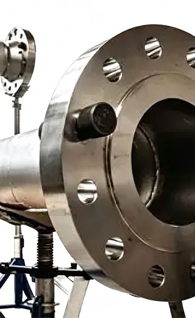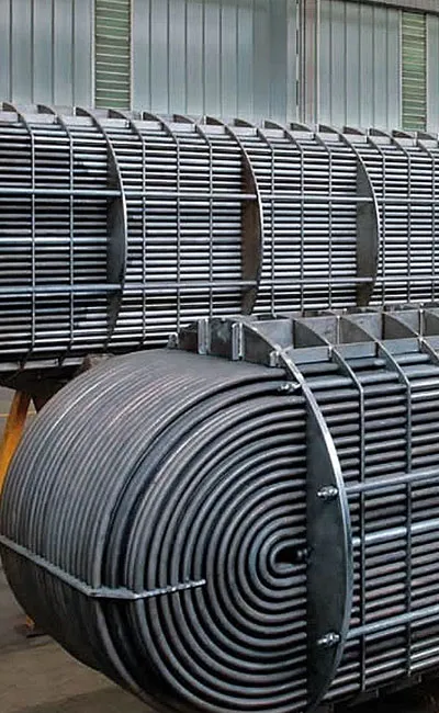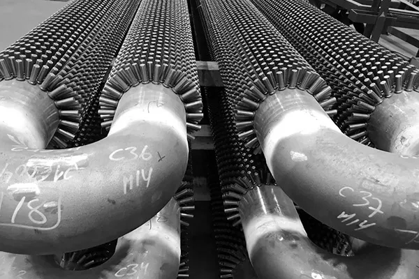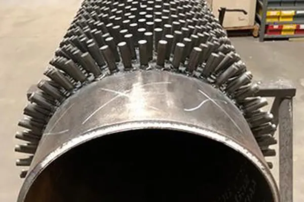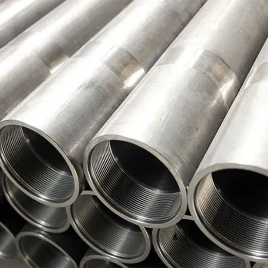

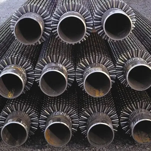
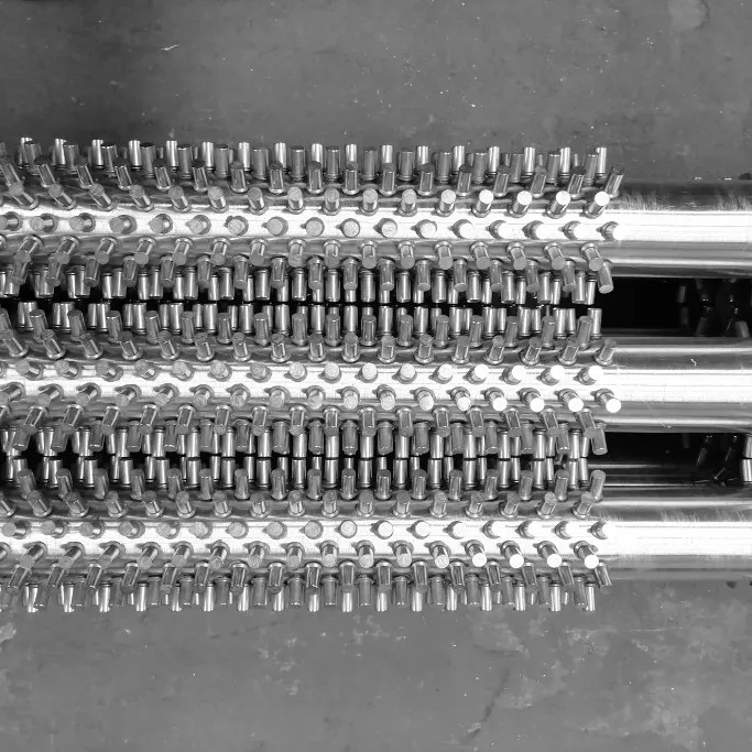
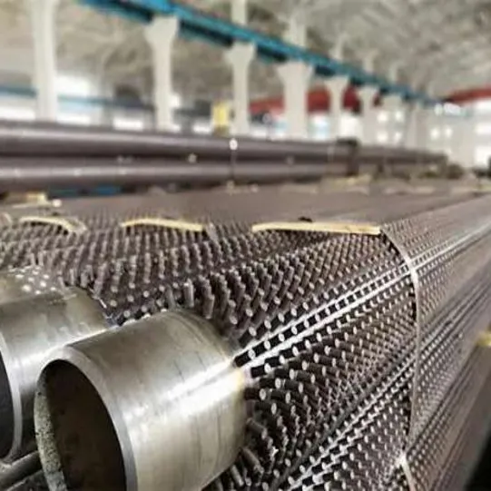
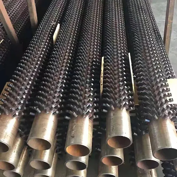
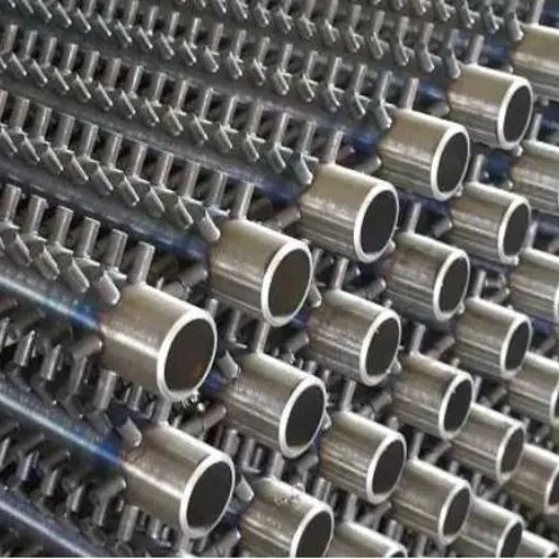
Studded tubes are specialized heat transfer components widely used in high-temperature industrial applications. They consist of a base tube (usually seamless or welded) with metal studs (pins) welded onto the external surface in a precise pattern. These studs serve two primary functions: they act as anchors to hold refractory material (castable) in place, protecting the tube from extreme heat and corrosion, and they significantly increase the surface area to enhance heat transfer efficiency in boiler systems.
Key Features:
• Refractory Anchoring: The studs provide a secure mechanical bond for fire-resistant lining, preventing it from falling off due to gravity or thermal shock.
• Enhanced Heat Transfer: The increased surface area improves the thermal exchange rate between the flue gas and the fluid inside the tube.
• Turbulence Generation: The studs disrupt the boundary layer of the gas flow, reducing fouling and improving efficiency.
• Corrosion Resistance: By allowing the use of specialized refractory materials, the base tube is shielded from corrosive combustion byproducts.
Applications:
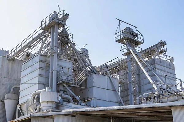
• Studded tubes are critical components in the energy and waste management sectors.
• Waste-to-Energy Plants: Used in the water walls and superheaters of incinerators to protect against acidic corrosion.
• Boiler Systems: Essential for Circulating Fluidized Bed (CFB) boilers and biomass boilers.
• Heat Recovery Steam Generators (HRSG): Used in the duct burners and evaporator sections.
• Petrochemical Industry: Applied in reformer furnaces and cracking furnaces.
• Steel Mills: Used in cooling systems for electric arc furnaces.
TheStudded Tube is manufactured to precise dimensional, material, and mechanical specifications to ensure reliable performance in high-temperature, high-pressure service. Below are the detailed specification tables.
Dimensional & Geometric Specification Table
|
Parameter |
Standard Range |
Customizable Range |
Tolerance / Notes |
|
Base Tube Outside Diameter (OD) |
38 – 219 mm |
20 – 426 mm |
Seamless or welded |
|
Base Tube Wall Thickness |
4.0 – 20 mm |
2.0 – 50 mm |
≥ Stud radius |
|
Base Tube Length |
≤ 15 m (standard) |
≤ 25 m |
Exact cut lengths available |
|
Stud Diameter |
6 – 12.5 mm |
3 – 25.4 mm |
Round, elliptical, lens type |
|
Stud Height |
10 – 35 mm |
5 – 50.8 mm |
Cylindrical/conical shapes |
|
Stud Longitudinal Pitch (Spacing) |
8 – 30 mm |
Custom by pattern |
Square or hexagonal arrangement |
|
Stud Pattern |
Staggered rows/rings |
Square or hexagonal |
Uniform heat distribution |
|
Stud Density |
120 – 400 studs/m² |
Adjustable by pitch |
Affects heat transfer area ratio |
|
Stud-to-Tube Angle |
90° (vertical) |
Angular |
Per customer specification |
|
Weld Penetration |
≥ 1.5 mm |
N/A |
Ensures strong metallurgical bond |
|
Weld Protrusion (Root Bulge) |
≤ 1 mm |
No-spatter standard |
Clean weld appearance |
Material Grade & Chemical Composition Table
|
Base Tube Material Standard |
Typical Grades |
Base Tube Material Class |
Stud Material Options |
|
ASTM A106 |
Gr.B |
Carbon Steel |
Q235B, AISI 410, 1Cr13, 2Cr13, 13Cr |
|
ASTM A179 / A192 |
— |
Carbon Steel |
Carbon steel, stainless steel |
|
ASTM A335 / ASME SA335 |
P5, P9, P11, P22, P91 |
Alloy Steel (Cr-Mo) |
Matching alloy or stainless |
|
ASTM A213 / ASME SA213 |
T5, T9, T11, T12, T22, T91 |
Alloy Steel (Cr-Mo) |
Matching alloy or stainless |
|
ASTM A312 / ASME SA312 |
TP304, TP304L, TP316, TP316L, TP321, TP347 |
Stainless Steel |
Stainless steel (e.g., SS304, SS316, SS409, SS410) |
|
API 5L |
Gr.B, X42, X52, X60, X65 |
Carbon Steel |
Carbon steel, stainless steel |
|
DIN / EN |
St35.8, St45.8, 13CrMo4-4, 10CrMo5-5 |
Various |
As required |
|
GB/T 8163 / GB 5310 |
20#, 45#, 12Cr1MoV, 15CrMo |
Carbon/Alloy Steel |
Q235B, 1Cr13, 2Cr13, 13Cr, SS304 |
Mechanical Properties & Operating Parameters Table
|
Parameter |
Carbon Steel Base Tube |
Alloy Steel Base Tube (Cr-Mo) |
Stainless Steel Base Tube |
|
Tensile Strength (min) |
≥ 410 – 490 MPa |
≥ 415 – 585 MPa (grade dependent) |
≥ 485 – 515 MPa |
|
Yield Strength (min) |
≥ 245 – 355 MPa |
≥ 205 – 415 MPa (grade dependent) |
≥ 170 – 205 MPa |
|
Elongation (min) |
≥ 20 – 25% |
≥ 20 – 30% |
≥ 35% |
|
Maximum Operating Temperature |
≤ 600°C |
≤ 650°C (T91: up to 650°C) |
≤ 800°C |
|
Maximum Operating Pressure |
≤ 16 MPa (standard) |
Higher capability |
As per alloy grade |
|
Heat Transfer Area Ratio |
2 – 3 × bare tube |
2 – 3 × bare tube |
2 – 3 × bare tube |
|
Hardness (max HBW) |
— |
163 – 250 |
179 – 192 |
The Studded Tube is manufactured and tested in compliance with a comprehensive range of international and national standards covering base tube materials, welding processes, and quality requirements.
Primary Standards for Studded Tubes
|
Standard / Code |
Full Title / Description |
Applicability |
|
ASTM A106 / ASME SA106 |
Seamless Carbon Steel Pipe for High-Temperature Service |
Base tube material for carbon steel studded tubes |
|
ASTM A179 / ASME SA179 |
Seamless Cold-Drawn Low-Carbon Steel Heat-Exchanger and Condenser Tubes |
Base tube material for heat exchanger applications |
|
ASTM A192 / ASME SA192 |
Seamless Carbon Steel Boiler Tubes for High Pressure |
Base tube material for boiler applications |
|
ASTM A335 / ASME SA335 |
Seamless Ferritic Alloy-Steel Pipe for High-Temperature Service |
Base tube material for alloy steel (Cr-Mo) studded tubes; covers P5, P9, P11, P22, P91 grades |
|
ASTM A213 / ASME SA213 |
Seamless Ferritic and Austenitic Alloy-Steel Boiler, Superheater, and Heat-Exchanger Tubes |
Base tube material for T-grade alloy and stainless studded tubes |
|
API 530 / API 660 |
Calculation of Heater-Tube Thickness in Petroleum Refineries / Shell-and-Tube Heat Exchangers |
Design and application standards for fired heaters and heat exchangers |
|
API Standard 661 |
Air-Cooled Heat Exchangers for General Refinery Service |
Acceptance criteria for finned and studded tube assemblies |
|
SH/T 3422-2011 |
Technical Specification for Stud Tubes of Tubular Heater in Petrochemical Engineering (China) |
Comprehensive Chinese standard covering structure, materials, welding, dimensions, manufacturing, testing, marking, packing, and shipping of studded tubes for petrochemical tubular heaters |
|
GB/T 8163 / GB 5310 |
Seamless Steel Tubes for Fluid Transport / Seamless Steel Tubes for High-Pressure Boilers |
Chinese base tube material standards |
|
ISO 9001:2015 |
Quality Management Systems |
Manufacturing quality certification |
Studded Tube vs. Finned Tube Comparison Table
|
Feature |
Studded Tube |
Finned Tube (HF Welded) |
|
Surface Geometry |
Discrete cylindrical/tapered studs |
Continuous helical fin |
|
Heat Transfer Area |
2–3× bare tube |
5–10× bare tube |
|
Fouling/Cleaning |
Easy to clean by shot blasting; self-cleaning via vibration |
Prone to fouling; difficult to clean |
|
Suitable Gas Streams |
Dirty, heavy particulate, corrosive flue gas (e.g., fuel oil firing) |
Clean gas streams (e.g., natural gas firing) |
|
Mechanical Strength |
High rigidity; withstands extreme conditions |
Moderate |
|
Pressure/Temperature Capability |
Very high (up to 300 bar / 800°C) |
Moderate |
|
Self-Cleaning Mechanism |
Cantilever stud design vibrates under gas flow (5–15 Hz), shedding ash |
No vibration mechanism |
|
Typical Applications |
Refinery fired heaters, CFB boilers, HRSG convection sections |
Air coolers, economizers, waste heat recovery |
|
Refractory Anchoring |
Yes (provides mechanical bond for refractory lining) |
No |
Key Quality Assurance Standards
• Welding Process Qualification: Resistance welding parameters (current, voltage, pressure, duration) are strictly controlled and recorded via PLC to ensure weld consistency and eliminate manual instability.
• Stress Relieving: Alloy steel pipes undergo post-weld heat treatment (PWHT) after studding according to the relevant specifications for the class and grade of steel used to relieve residual stresses and prevent hydrogen-induced cracking.
• Inspection: Third-party inspection (SGS, BV, TÜV) is available. EN 10204 Type 3.2 certificates can be provided for project-specific requirements.
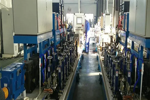
The manufacturing process of Studded Tubes utilizes automated resistance welding technology to achieve consistent, high-integrity stud-to-tube bonds with minimal heat input and no filler material.
Step 1–Base Tube Preparation: Seamless or welded base tubes (carbon, alloy, or stainless steel) are cut to specified length, with ends square-cut, deburred, and internally blown clean of debris. Tubes are inspected for dimensional accuracy and surface defects prior to studding. Alloy steel tubes are handled according to their specific material grade requirements.
Step 2–Stud Material Preparation: Forged steel studs (cylindrical, elliptical, or lens-shaped) are produced to the specified diameter (3–25.4 mm) and height (5–50.8 mm). Studs may be supplied in carbon steel (e.g., Q235B), stainless steel (e.g., AISI 304, 316, 409, 410, 321, 347), or alloy steel grades matching the base tube material. The studs are specifically shaped to facilitate the resistance welding process and enhance the mechanical bond.
Step 3–Automatic Resistance Welding (Core Process): The base tube is fixtured in an automatic studded tube welding machine. The welding process operates on the principle of electrical resistance: an electric current is passed through the contact point between the stud and the tube. The resistance at this interface generates intense, localized heat. Pressure (applied via tooling) forges the stud and tube together at the point of maximum heating, creating a high-quality metallurgical forge weld. The welding parameters (current, voltage, pressure, duration) are controlled by a PLC program, with feed motor and graduation servo motor ensuring precise stud placement. The entire process uses no external heat source; all heat is generated by electrical resistance at the interface. This results in a very localized heat-affected zone (HAZ) in the base tube, with narrow surface heating that does not destroy the underlying microstructure of the base material. Post-weld heat treatment (stress relieving) is generally not considered necessary for carbon steel due to the superficial nature of the microstructural changes. However, alloy steel pipes are stress-relieved after studding according to the relevant specifications for the class and grade of steel used.
Step 4–Welding Pattern Formation: Studs are welded onto the base tube in staggered rows (rings) around the circumference, arranged in square or hexagonal patterns with adjustable longitudinal spacing (8–30 mm). Symmetric distribution ensures uniform heat transfer and enables vibration-driven self-cleaning. The welding process achieves penetration≥1.5 mm and weld protrusion≤1 mm (no-spatter standard).
Step 5–Quality Inspection & Testing: Welding tests are carried out as a matter of course to ensure the effectiveness of the stud-to-pipe bond. Alloy steel pipes are stress-relieved after studding per relevant specifications. If required, external surfaces can be treated with protective coating. Heat treatment of the completed studded tube is carried out where necessary. Studded tubes may be subjected to hydrostatic testing at 1.5×design pressure to verify leak-tightness.
Step 6–Surface Finishing & Protection: Studded tubes may be provided with a protective coating on external surfaces if required. Tube ends are left plain or beveled per customer specification. End caps are applied to prevent contamination during storage and transport.
Proper packing ofStudded Tubesis essential to prevent damage to the welded studs, base tube surface scratching, moisture ingress, and corrosion during transit and long-term storage. The protruding studs are particularly vulnerable to impact damage and require careful handling.
End Protection: Plastic caps are plugged at both ends of each tube to prevent foreign objects (dust, debris, moisture) from entering the tube bore. For threaded or beveled ends, specialized end caps are applied. Studded tubes are protected from steel strapping and transport damage through the use of protective padding and separation materials.
Bundling & Separation: Studded tubes are packed in bundles with uniform and consistent labeling. Tubes within the same bundle must originate from the same heat/furnace batch, with the same steel grade and the same specifications to ensure traceability. Wooden battens, foam padding, or non-woven fabric strips (thickness≥5 mm) are placed between individual tubes to prevent metal-to-metal contact, which could damage the studs or scratch the tube surface. Bundles are secured with steel strapping, with cardboard or plastic strips placed under each strap to prevent direct contact with the tube surface.
Crating for Export: For sea freight or high-value orders, studded tubes are packed in seaworthy wooden crates (ISPM 15 certified for export) or steel crates. The crate interior is lined with waterproof polyethylene film, and desiccant bags (silica gel, 500 g each) are placed inside to absorb moisture. Foam padding or wood blocking fills voids to prevent tube movement during transit. Corner protectors are added to safeguard tube ends and studded sections. The base tube ends are square cut, free of burrs, and the inside is dry and blown clean before packing. For extruded bimetallic studded tubes, the external surfaces may be coated with varnish.
Labeling: Each bundle or crate carries a waterproof label showing customer PO number, base tube grade, stud material, dimensions (OD×length), stud pattern/density, quantity, heat number, net weight, and handling symbols (“KEEP DRY”,“FRAGILE–PROTECT STUDS”,“USE SOFT SLINGS”,“DO NOT ROLL”). A detailed packing list is enclosed in a waterproof sleeve attached to the crate or bundle.
A: Studded tubes have discrete cylindrical or tapered studs welded onto the base tube surface, while finned tubes have a continuous helical fin wound around the tube. Studded tubes offer superior self-cleaning properties and are easier to clean by shot blasting; they are preferred for dirty gas streams (e.g., fuel oil-fired heaters, CFB boilers) where heavy fouling may occur. Finned tubes provide a larger surface area and are more suitable for clean gas streams (e.g., natural gas firing) where fouling is minimal. The heat transfer efficiency of studded tubes is equivalent to 2–3 times that of a bare tube.
A: Studded tubes can be manufactured with any combination of stud and tube materials, including carbon steel (ASTM A106 Gr.B, A179, API 5L Gr.B), alloy steel (ASTM A335 P5, P9, P11, P22, P91 / A213 T5, T9, T11, T22, T91), stainless steel (ASTM A312 TP304, 316, 321, 347), and high nickel alloys. Stud materials can be selected independently from the base tube material (e.g., stainless steel studs on carbon steel tubes).
A: For carbon steel base tubes, maximum service temperature is approximately 600°C. Alloy steel Cr-Mo grades (P11, P22) are suitable up to ~565°C, while P91/T91 can operate up to 650°C. Stainless steel grades (304, 316) can withstand up to 800°C. For applications requiring operation above 800°C, nickel-based alloys are recommended.
A: Standard sizes with common material combinations (carbon steel base + carbon steel studs) can be shipped within 3–4 weeks. Custom orders (alloy steel grades, non-standard stud patterns/dimensions, special materials) typically require 5–8 weeks depending on quantity and complexity. Expedited production may be available with a surcharge.
A: Yes. We can provide EN 10204 Type 3.1 mill test certificates with full traceability to heat number. Third-party inspection services (SGS, BV, TÜV) are available upon request. Alloy steel tubes are stress-relieved after studding according to relevant specifications. We also comply with ISO 9001:2015 quality management standards.
TheStudded Tube is manufactured to precise dimensional, material, and mechanical specifications to ensure reliable performance in high-temperature, high-pressure service. Below are the detailed specification tables.
Dimensional & Geometric Specification Table
|
Parameter |
Standard Range |
Customizable Range |
Tolerance / Notes |
|
Base Tube Outside Diameter (OD) |
38 – 219 mm |
20 – 426 mm |
Seamless or welded |
|
Base Tube Wall Thickness |
4.0 – 20 mm |
2.0 – 50 mm |
≥ Stud radius |
|
Base Tube Length |
≤ 15 m (standard) |
≤ 25 m |
Exact cut lengths available |
|
Stud Diameter |
6 – 12.5 mm |
3 – 25.4 mm |
Round, elliptical, lens type |
|
Stud Height |
10 – 35 mm |
5 – 50.8 mm |
Cylindrical/conical shapes |
|
Stud Longitudinal Pitch (Spacing) |
8 – 30 mm |
Custom by pattern |
Square or hexagonal arrangement |
|
Stud Pattern |
Staggered rows/rings |
Square or hexagonal |
Uniform heat distribution |
|
Stud Density |
120 – 400 studs/m² |
Adjustable by pitch |
Affects heat transfer area ratio |
|
Stud-to-Tube Angle |
90° (vertical) |
Angular |
Per customer specification |
|
Weld Penetration |
≥ 1.5 mm |
N/A |
Ensures strong metallurgical bond |
|
Weld Protrusion (Root Bulge) |
≤ 1 mm |
No-spatter standard |
Clean weld appearance |
Material Grade & Chemical Composition Table
|
Base Tube Material Standard |
Typical Grades |
Base Tube Material Class |
Stud Material Options |
|
ASTM A106 |
Gr.B |
Carbon Steel |
Q235B, AISI 410, 1Cr13, 2Cr13, 13Cr |
|
ASTM A179 / A192 |
— |
Carbon Steel |
Carbon steel, stainless steel |
|
ASTM A335 / ASME SA335 |
P5, P9, P11, P22, P91 |
Alloy Steel (Cr-Mo) |
Matching alloy or stainless |
|
ASTM A213 / ASME SA213 |
T5, T9, T11, T12, T22, T91 |
Alloy Steel (Cr-Mo) |
Matching alloy or stainless |
|
ASTM A312 / ASME SA312 |
TP304, TP304L, TP316, TP316L, TP321, TP347 |
Stainless Steel |
Stainless steel (e.g., SS304, SS316, SS409, SS410) |
|
API 5L |
Gr.B, X42, X52, X60, X65 |
Carbon Steel |
Carbon steel, stainless steel |
|
DIN / EN |
St35.8, St45.8, 13CrMo4-4, 10CrMo5-5 |
Various |
As required |
|
GB/T 8163 / GB 5310 |
20#, 45#, 12Cr1MoV, 15CrMo |
Carbon/Alloy Steel |
Q235B, 1Cr13, 2Cr13, 13Cr, SS304 |
Mechanical Properties & Operating Parameters Table
|
Parameter |
Carbon Steel Base Tube |
Alloy Steel Base Tube (Cr-Mo) |
Stainless Steel Base Tube |
|
Tensile Strength (min) |
≥ 410 – 490 MPa |
≥ 415 – 585 MPa (grade dependent) |
≥ 485 – 515 MPa |
|
Yield Strength (min) |
≥ 245 – 355 MPa |
≥ 205 – 415 MPa (grade dependent) |
≥ 170 – 205 MPa |
|
Elongation (min) |
≥ 20 – 25% |
≥ 20 – 30% |
≥ 35% |
|
Maximum Operating Temperature |
≤ 600°C |
≤ 650°C (T91: up to 650°C) |
≤ 800°C |
|
Maximum Operating Pressure |
≤ 16 MPa (standard) |
Higher capability |
As per alloy grade |
|
Heat Transfer Area Ratio |
2 – 3 × bare tube |
2 – 3 × bare tube |
2 – 3 × bare tube |
|
Hardness (max HBW) |
— |
163 – 250 |
179 – 192 |
The Studded Tube is manufactured and tested in compliance with a comprehensive range of international and national standards covering base tube materials, welding processes, and quality requirements.
Primary Standards for Studded Tubes
|
Standard / Code |
Full Title / Description |
Applicability |
|
ASTM A106 / ASME SA106 |
Seamless Carbon Steel Pipe for High-Temperature Service |
Base tube material for carbon steel studded tubes |
|
ASTM A179 / ASME SA179 |
Seamless Cold-Drawn Low-Carbon Steel Heat-Exchanger and Condenser Tubes |
Base tube material for heat exchanger applications |
|
ASTM A192 / ASME SA192 |
Seamless Carbon Steel Boiler Tubes for High Pressure |
Base tube material for boiler applications |
|
ASTM A335 / ASME SA335 |
Seamless Ferritic Alloy-Steel Pipe for High-Temperature Service |
Base tube material for alloy steel (Cr-Mo) studded tubes; covers P5, P9, P11, P22, P91 grades |
|
ASTM A213 / ASME SA213 |
Seamless Ferritic and Austenitic Alloy-Steel Boiler, Superheater, and Heat-Exchanger Tubes |
Base tube material for T-grade alloy and stainless studded tubes |
|
API 530 / API 660 |
Calculation of Heater-Tube Thickness in Petroleum Refineries / Shell-and-Tube Heat Exchangers |
Design and application standards for fired heaters and heat exchangers |
|
API Standard 661 |
Air-Cooled Heat Exchangers for General Refinery Service |
Acceptance criteria for finned and studded tube assemblies |
|
SH/T 3422-2011 |
Technical Specification for Stud Tubes of Tubular Heater in Petrochemical Engineering (China) |
Comprehensive Chinese standard covering structure, materials, welding, dimensions, manufacturing, testing, marking, packing, and shipping of studded tubes for petrochemical tubular heaters |
|
GB/T 8163 / GB 5310 |
Seamless Steel Tubes for Fluid Transport / Seamless Steel Tubes for High-Pressure Boilers |
Chinese base tube material standards |
|
ISO 9001:2015 |
Quality Management Systems |
Manufacturing quality certification |
Studded Tube vs. Finned Tube Comparison Table
|
Feature |
Studded Tube |
Finned Tube (HF Welded) |
|
Surface Geometry |
Discrete cylindrical/tapered studs |
Continuous helical fin |
|
Heat Transfer Area |
2–3× bare tube |
5–10× bare tube |
|
Fouling/Cleaning |
Easy to clean by shot blasting; self-cleaning via vibration |
Prone to fouling; difficult to clean |
|
Suitable Gas Streams |
Dirty, heavy particulate, corrosive flue gas (e.g., fuel oil firing) |
Clean gas streams (e.g., natural gas firing) |
|
Mechanical Strength |
High rigidity; withstands extreme conditions |
Moderate |
|
Pressure/Temperature Capability |
Very high (up to 300 bar / 800°C) |
Moderate |
|
Self-Cleaning Mechanism |
Cantilever stud design vibrates under gas flow (5–15 Hz), shedding ash |
No vibration mechanism |
|
Typical Applications |
Refinery fired heaters, CFB boilers, HRSG convection sections |
Air coolers, economizers, waste heat recovery |
|
Refractory Anchoring |
Yes (provides mechanical bond for refractory lining) |
No |
Key Quality Assurance Standards
• Welding Process Qualification: Resistance welding parameters (current, voltage, pressure, duration) are strictly controlled and recorded via PLC to ensure weld consistency and eliminate manual instability.
• Stress Relieving: Alloy steel pipes undergo post-weld heat treatment (PWHT) after studding according to the relevant specifications for the class and grade of steel used to relieve residual stresses and prevent hydrogen-induced cracking.
• Inspection: Third-party inspection (SGS, BV, TÜV) is available. EN 10204 Type 3.2 certificates can be provided for project-specific requirements.
The manufacturing process of Studded Tubes utilizes automated resistance welding technology to achieve consistent, high-integrity stud-to-tube bonds with minimal heat input and no filler material.
Step 1–Base Tube Preparation: Seamless or welded base tubes (carbon, alloy, or stainless steel) are cut to specified length, with ends square-cut, deburred, and internally blown clean of debris. Tubes are inspected for dimensional accuracy and surface defects prior to studding. Alloy steel tubes are handled according to their specific material grade requirements.
Step 2–Stud Material Preparation: Forged steel studs (cylindrical, elliptical, or lens-shaped) are produced to the specified diameter (3–25.4 mm) and height (5–50.8 mm). Studs may be supplied in carbon steel (e.g., Q235B), stainless steel (e.g., AISI 304, 316, 409, 410, 321, 347), or alloy steel grades matching the base tube material. The studs are specifically shaped to facilitate the resistance welding process and enhance the mechanical bond.
Step 3–Automatic Resistance Welding (Core Process): The base tube is fixtured in an automatic studded tube welding machine. The welding process operates on the principle of electrical resistance: an electric current is passed through the contact point between the stud and the tube. The resistance at this interface generates intense, localized heat. Pressure (applied via tooling) forges the stud and tube together at the point of maximum heating, creating a high-quality metallurgical forge weld. The welding parameters (current, voltage, pressure, duration) are controlled by a PLC program, with feed motor and graduation servo motor ensuring precise stud placement. The entire process uses no external heat source; all heat is generated by electrical resistance at the interface. This results in a very localized heat-affected zone (HAZ) in the base tube, with narrow surface heating that does not destroy the underlying microstructure of the base material. Post-weld heat treatment (stress relieving) is generally not considered necessary for carbon steel due to the superficial nature of the microstructural changes. However, alloy steel pipes are stress-relieved after studding according to the relevant specifications for the class and grade of steel used.
Step 4–Welding Pattern Formation: Studs are welded onto the base tube in staggered rows (rings) around the circumference, arranged in square or hexagonal patterns with adjustable longitudinal spacing (8–30 mm). Symmetric distribution ensures uniform heat transfer and enables vibration-driven self-cleaning. The welding process achieves penetration≥1.5 mm and weld protrusion≤1 mm (no-spatter standard).
Step 5–Quality Inspection & Testing: Welding tests are carried out as a matter of course to ensure the effectiveness of the stud-to-pipe bond. Alloy steel pipes are stress-relieved after studding per relevant specifications. If required, external surfaces can be treated with protective coating. Heat treatment of the completed studded tube is carried out where necessary. Studded tubes may be subjected to hydrostatic testing at 1.5×design pressure to verify leak-tightness.
Step 6–Surface Finishing & Protection: Studded tubes may be provided with a protective coating on external surfaces if required. Tube ends are left plain or beveled per customer specification. End caps are applied to prevent contamination during storage and transport.
Proper packing ofStudded Tubesis essential to prevent damage to the welded studs, base tube surface scratching, moisture ingress, and corrosion during transit and long-term storage. The protruding studs are particularly vulnerable to impact damage and require careful handling.
End Protection: Plastic caps are plugged at both ends of each tube to prevent foreign objects (dust, debris, moisture) from entering the tube bore. For threaded or beveled ends, specialized end caps are applied. Studded tubes are protected from steel strapping and transport damage through the use of protective padding and separation materials.
Bundling & Separation: Studded tubes are packed in bundles with uniform and consistent labeling. Tubes within the same bundle must originate from the same heat/furnace batch, with the same steel grade and the same specifications to ensure traceability. Wooden battens, foam padding, or non-woven fabric strips (thickness≥5 mm) are placed between individual tubes to prevent metal-to-metal contact, which could damage the studs or scratch the tube surface. Bundles are secured with steel strapping, with cardboard or plastic strips placed under each strap to prevent direct contact with the tube surface.
Crating for Export: For sea freight or high-value orders, studded tubes are packed in seaworthy wooden crates (ISPM 15 certified for export) or steel crates. The crate interior is lined with waterproof polyethylene film, and desiccant bags (silica gel, 500 g each) are placed inside to absorb moisture. Foam padding or wood blocking fills voids to prevent tube movement during transit. Corner protectors are added to safeguard tube ends and studded sections. The base tube ends are square cut, free of burrs, and the inside is dry and blown clean before packing. For extruded bimetallic studded tubes, the external surfaces may be coated with varnish.
Labeling: Each bundle or crate carries a waterproof label showing customer PO number, base tube grade, stud material, dimensions (OD×length), stud pattern/density, quantity, heat number, net weight, and handling symbols (“KEEP DRY”,“FRAGILE–PROTECT STUDS”,“USE SOFT SLINGS”,“DO NOT ROLL”). A detailed packing list is enclosed in a waterproof sleeve attached to the crate or bundle.
A: Studded tubes have discrete cylindrical or tapered studs welded onto the base tube surface, while finned tubes have a continuous helical fin wound around the tube. Studded tubes offer superior self-cleaning properties and are easier to clean by shot blasting; they are preferred for dirty gas streams (e.g., fuel oil-fired heaters, CFB boilers) where heavy fouling may occur. Finned tubes provide a larger surface area and are more suitable for clean gas streams (e.g., natural gas firing) where fouling is minimal. The heat transfer efficiency of studded tubes is equivalent to 2–3 times that of a bare tube.
A: Studded tubes can be manufactured with any combination of stud and tube materials, including carbon steel (ASTM A106 Gr.B, A179, API 5L Gr.B), alloy steel (ASTM A335 P5, P9, P11, P22, P91 / A213 T5, T9, T11, T22, T91), stainless steel (ASTM A312 TP304, 316, 321, 347), and high nickel alloys. Stud materials can be selected independently from the base tube material (e.g., stainless steel studs on carbon steel tubes).
A: For carbon steel base tubes, maximum service temperature is approximately 600°C. Alloy steel Cr-Mo grades (P11, P22) are suitable up to ~565°C, while P91/T91 can operate up to 650°C. Stainless steel grades (304, 316) can withstand up to 800°C. For applications requiring operation above 800°C, nickel-based alloys are recommended.
A: Standard sizes with common material combinations (carbon steel base + carbon steel studs) can be shipped within 3–4 weeks. Custom orders (alloy steel grades, non-standard stud patterns/dimensions, special materials) typically require 5–8 weeks depending on quantity and complexity. Expedited production may be available with a surcharge.
A: Yes. We can provide EN 10204 Type 3.1 mill test certificates with full traceability to heat number. Third-party inspection services (SGS, BV, TÜV) are available upon request. Alloy steel tubes are stress-relieved after studding according to relevant specifications. We also comply with ISO 9001:2015 quality management standards.


 English
 Español
 русский язык
 Português