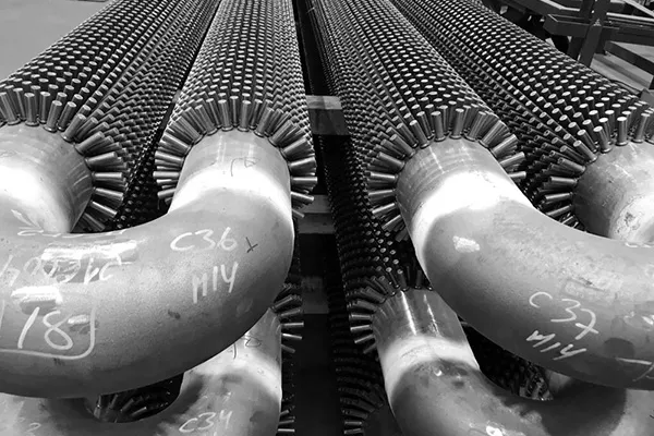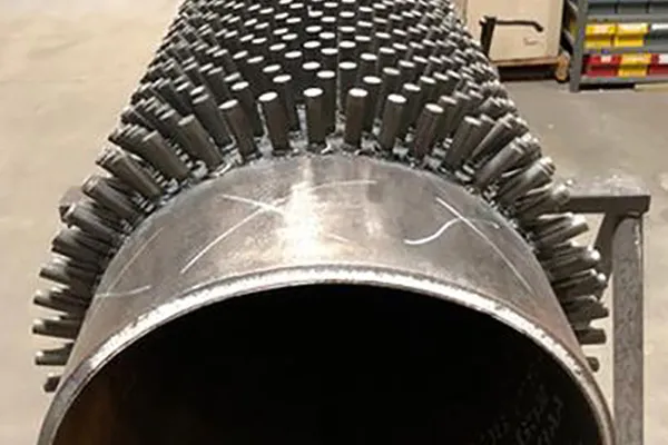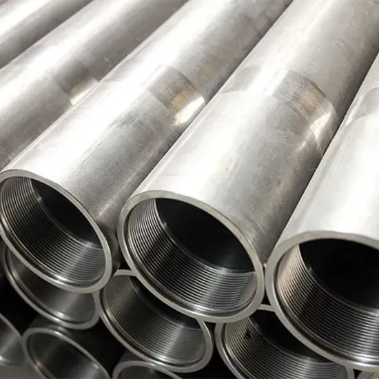

TheFinned Steel Tube(also known as a finned tube, fin pipe, or extended surface tube) is a high-performance heat transfer component manufactured by attaching continuous metal fins—either solid or serrated—to the outer surface of a seamless or welded base tube. The fins dramatically increase the tube's external surface area, typically by 4 to 10 times compared to a bare (plain) tube, thereby significantly enhancing heat exchange efficiency between the tube wall and the surrounding fluid—most commonly air or flue gas. Among the various manufacturing methods available, high-frequency resistance welding (HFW) has emerged as the industry standard for producing finned tubes that combine strong metallurgical bonds with excellent thermal performance.
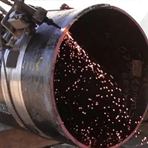
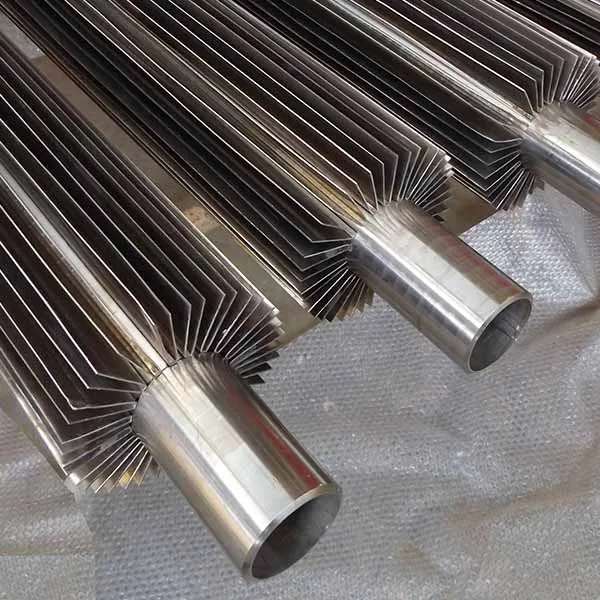
High-frequencywelded fin tubesare produced by helically wrapping a continuous fin strip (carbon steel, stainless steel, or other alloys) around the base tube while applying high-frequency electric current (typically 200–450 kHz) to the interface. The electrical resistance at the contact point generates intense localized heat, instantly bringing the metal to a molten state (1200–1400°C) without melting the filler material, while a forging pressure of 0.8–1.5 MPa is applied to achieve a continuous metallurgical bond. The result is a fin-to-tube attachment with tensile strength approaching that of the base materials themselves, offering superior durability under thermal cycling and vibration. HFW fin tubes are available in two primary fin types: solid (flat) fins for general-purpose applications and serrated (toothed) fins that create turbulence, breaking the boundary layer for an additional 35–45% increase in the heat transfer coefficient compared to standard solid fins. The effective heat transfer area can be expanded to 4–10 times that of a plain tube, with thermal conductivity of approximately 15.1 W/(m·K) for stainless steel grades.
Applications:
Finned steel tubes are indispensable across virtually every industry that relies on thermal management.
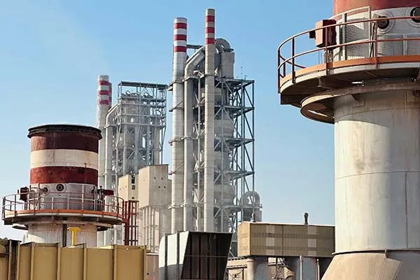
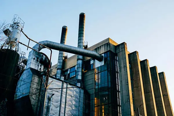
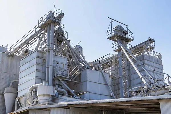
• In power generation, they serve in boiler economizers, steam condensers, air preheaters, superheaters, and waste heat recovery systems, recovering heat from flue gases that would otherwise be lost.
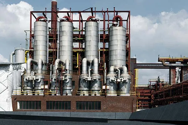
• In petrochemical and chemical processing plants, finned tubes are used in heat exchangers, reactors, reboilers, distillation columns, and process heaters, handling aggressive chemicals and high-temperature conditions.
• Oil refineries employ them in crude oil heaters, gas coolers, and LNG vaporization systems.
• In HVAC and refrigeration systems, finned tubes function as condensers, evaporators, and air handling units for building climate control. Additional applications include food and beverage processing (pasteurization, fermentation temperature control), automotive radiators and charge air coolers, marine seawater coolers, aircraft environmental control systems, pharmaceutical sterilization, and renewable energy technologies such as solar thermal collectors and biomass boilers.
The Finned Steel Tube is manufactured to precise dimensional, material, and mechanical specifications to ensure reliable performance in high-temperature and high-pressure heat transfer service.
Dimensional Specification Table
|
Parameter |
Range |
Tolerance / Notes |
|
Base Tube Outside Diameter (OD) |
10 – 219 mm (standard); up to 500 mm (custom) |
±0.5 mm (hot-rolled); ±0.1 mm (cold-drawn) |
|
Base Tube Wall Thickness (WT) |
1.0 – 12.0 mm (standard); up to 30 mm (special) |
±10% of nominal |
|
Base Tube Length |
3 m – 15 m (standard); up to 18 m (custom) |
±1 mm (≤6 m); ±2 mm (>6 m) |
|
Fin Type |
Solid (flat) / Serrated (toothed) / Helical spiral |
Continuous helix |
|
Fin Material |
Carbon steel, stainless steel, aluminum, copper |
Compatible with base tube |
|
Fin Height |
8 – 25 mm (standard); 6 – 50 mm (custom) |
±0.5 mm |
|
Fin Thickness |
0.8 – 2.5 mm (standard); 0.5 – 4.0 mm (custom) |
±0.05 mm |
|
Fin Pitch |
4 – 20 mm (standard); 2 – 25 mm (custom) |
±0.2 mm |
|
Fin Density |
1.2 – 6.0 fins per inch (FPI) (typical) |
Low: 1-2 FPI; Medium: 3-5 FPI; High: 6-8 FPI |
|
Surface Area Ratio |
4 – 10 × bare tube (depending on fin geometry) |
Higher for high-density, high-height fins |
|
Welding Frequency |
200 – 450 kHz |
Controlled per HFW process |
|
Welding Speed |
15 – 40 m/min |
Affects bond integrity |
Material Grade & Chemical Composition Table
|
Base Tube Standard |
Base Tube Grade |
Fin Material Options |
Fin Material Grade |
Key Characteristics |
|
ASTM A179 |
Seamless low-carbon steel |
Carbon steel / Aluminum |
Q235B / AL1060 |
Most economical; suitable for general heat exchanger service up to 400°C |
|
ASTM A192 |
Seamless carbon steel (high pressure) |
Carbon steel / Stainless steel |
Q235B / SS304 |
High-pressure boiler applications |
|
ASTM A106 |
Gr.B seamless carbon steel |
Carbon steel / Stainless steel |
Q235B / SS304/316 |
High-temperature service; API 5L equivalent |
|
ASTM A213 |
T11, T22, T91 (alloy Cr-Mo) |
Alloy steel / Stainless steel |
Matching grade / SS304/316 |
Creep-resistant for 550-650°C service |
|
ASTM A213 |
TP304, TP304L (stainless steel) |
Stainless steel |
SS304 / SS304L |
Corrosion-resistant; food/pharma grade |
|
ASTM A213 |
TP316, TP316L (stainless steel) |
Stainless steel |
SS316 / SS316L |
Superior chloride resistance; marine/chemical applications |
|
EN 10216-2 |
P235GH, P265GH, 16Mo3 |
Carbon steel / Stainless steel |
As required |
European standard; CE-marked for PED |
|
GB 5310 |
20G, 15CrMoG, 12Cr1MoVG |
Carbon steel / Alloy steel |
As required |
Chinese national standard for high-pressure boilers |
Mechanical & Thermal Performance Table
|
Parameter |
Carbon Steel (A179) |
Alloy Steel (T11/T22) |
Stainless Steel (TP304/316L) |
|
Base Tube Tensile Strength (min) |
325 MPa |
415 – 585 MPa |
485 – 515 MPa |
|
Base Tube Yield Strength (min) |
180 MPa |
205 – 415 MPa |
170 – 205 MPa |
|
Base Tube Elongation (min) |
35% |
20 – 30% |
35 – 40% |
|
Max Continuous Operating Temperature |
~400°C |
~565°C (T22); ~650°C (T91) |
~750°C |
|
Thermal Conductivity |
~45 W/(m·K) |
~35 – 40 W/(m·K) |
~15 – 16 W/(m·K) |
|
Heat Transfer Coefficient (HFW solid fin) |
250 – 350 W/m²·K |
250 – 350 W/m²·K |
250 – 350 W/m²·K |
|
Heat Transfer Coefficient (HFW serrated fin) |
380 – 500 W/m²·K |
380 – 500 W/m²·K |
380 – 500 W/m²·K |
|
Thermal Efficiency Improvement |
25 – 45% over solid fin |
25 – 45% over solid fin |
25 – 45% over solid fin |
Our finned steel tubes are manufactured in compliance with major international standards, ensuring safety, reliability, and performance in critical applications.
|
Standard |
Description |
Common Grades |
|
ASTM A179 |
Seamless Cold-Drawn Low-Carbon Steel Heat-Exchanger and Condenser Tubes |
Grade 1010, 1020 |
|
ASTM A192 |
Seamless Carbon Steel Boiler and Superheater Tubes for High-Pressure Service |
Grade 1015, 1025 |
|
ASTM A210 |
Seamless Medium-Carbon Steel Boiler and Superheater Tubes |
Grade A1, C |
|
ASTM A213 |
Seamless Ferritic and Austenitic Alloy-Steel Boiler, Superheater, and Heat-Exchanger Tubes |
T11, T22, TP304, TP321 |
|
ASTM A335 |
Seamless Ferritic Alloy-Steel Pipe for High-Temperature Service |
P11, P22, P91 |
Fin Material Standards:
|
Material |
Standard |
Application |
|
Carbon Steel Strip |
ASTM A1008 / A1011 |
General heat exchange, economizers. |
|
Stainless Steel Strip |
ASTM A240 (304, 316, 321) |
Corrosive environments, high-temp superheaters. |
|
Aluminum Strip |
ASTM B209 (1100, 3003) |
Air coolers where weight reduction is needed. |
Finishing & Testing Standards:
|
Standard |
Description |
|
ASME Section I |
Power Boilers (Rules for construction). |
|
ASME Section VIII |
Pressure Vessels. |
|
HEI |
Heat Exchange Institute Standards. |
|
TEMA |
Tubular Exchanger Manufacturers Association. |
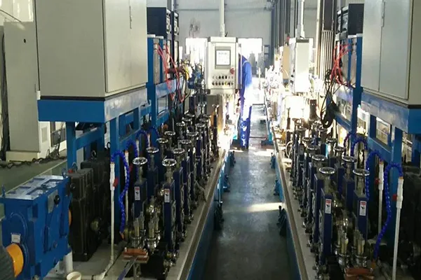
The manufacturing process of Finned Steel Tubes utilizes high-frequency resistance welding (HFRW) technology to achieve consistent, high-quality fin-to-tube bonds with minimal heat input and no filler material.
Step 1–Base Tube Preparation: The seamless or welded base tube (carbon steel, alloy steel, or stainless steel) is cut to the specified length and inspected for dimensional accuracy and surface defects. The tube surface is cleaned to remove oil, rust, and contaminants; straightened to prevent misalignment of the spiral fins; and ends are prepared for the fin welding process.
Step 2–Fin Strip Preparation: A continuous metal strip (carbon steel, stainless steel, aluminum, or other alloy) is precision-formed to the required fin thickness. For serrated (toothed) fins, the metal strip is slit or cut at regular intervals before wrapping to create the toothed geometry that promotes turbulence and enhances heat transfer.
Step 3–High-Frequency Resistance Welding (Core Process): The base tube is fixtured in an automated HFW fin tube machine. The fin strip is helically wrapped around the tube with precise pitch control. As the fin edge passes through a high-frequency coil or welding head, high-frequency electric current (200–450 kHz) is applied to the interface. Due to the electrical resistance at the contact point, intense localized heat is generated, raising the metal temperature to 1200–1400°C and bringing the interface to a molten state. Simultaneously, a forging pressure of 0.8–1.5 MPa is applied by pressure rollers, forcing the molten fin material into the tube surface and creating a continuous metallurgical bond along the entire length of the spiral seam. The process is fully automated via PLC control, with programmable parameters (feed motor, graduation servo motor) ensuring consistent fin placement, penetration, and minimal weld protrusion. The entire operation requires no external heat source or filler material.
Step 4–Cooling & Solidification: The welded fin tube is immediately cooled, typically via water spray or forced air, to solidify the weld joint and lock in the fin geometry.
Step 5–Post-Weld Heat Treatment (PWHT): For alloy steel base tubes (e.g., T11, T22, T91), stress relieving or full annealing may be performed after fin welding according to relevant specifications to relieve residual stresses and prevent hydrogen-induced cracking.
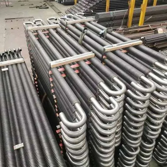
Step 6–Straightening & Finishing: The finned tube is straightened and passed through sizing rolls as needed. Tube ends are cut to final length, and the finned section is trimmed at the ends to leave a bare pipe section for welding or flanging (typically 50–150 mm at each end).
Step 7–Quality Inspection: 100% visual inspection of the weld seam is performed. For critical applications, additional NDE (eddy current or ultrasonic testing) is conducted. Dimensional verification includes fin height, fin pitch, base tube OD and wall thickness. Weld integrity is verified via destructive testing (peel test) on sample coupons.
Step 8–Surface Finishing & Marking: Carbon steel tubes receive a rust-preventive coating. Each tube is marked with grade, size, heat number, fin type/specification, and standard. EN 10204 Type 3.1 mill test certificates are provided.
Proper packing of Finned Steel Tubes is essential to prevent fin damage, base tube scratching, moisture ingress, and corrosion during transit and long-term storage. The protruding fins are particularly vulnerable to impact damage and require careful handling.
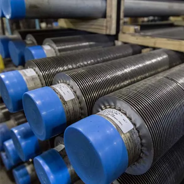
End Protection: Plastic caps are plugged at both ends of each tube to prevent foreign objects (dust, debris, moisture) from entering the tube bore. For flanged or threaded ends, specialized end caps are applied.
Surface Protection & Rust Prevention: Carbon steel finned tubes are coated with a thin layer of rust-preventive oil on internal and external surfaces. For export shipments or high-humidity destinations, each tube is wrapped with VCI (Volatile Corrosion Inhibitor) paper or polyethylene film. Desiccant bags (silica gel, 500 g) are placed inside the tube bore. A protective coating can be applied before storage to provide an extra layer of protection against moisture and environmental factors.
Bundling & Separation: Finned tubes are packed in bundles with uniform labeling. Wooden battens, foam padding, or non-woven fabric strips (thickness≥5 mm) are placed between individual tubes to prevent metal-to-metal contact, which could damage the fins or scratch the tube surface. Tubes are carefully arranged inside the crate or frame to avoid any contact that could cause scratches or dents. Bundles are secured with steel strapping, with cardboard or plastic strips placed under each strap to prevent direct contact with the tube surface.
Crating for Export: For sea freight or high-value orders, finned tubes are packed in seaworthy wooden crates (ISPM 15 certified for export) or steel frames. Crates are specifically engineered to fit the product shape, with wider-than-tall designs to prevent tipping during transit. The crate interior is lined with waterproof polyethylene film, and foam padding or wood blocking fills voids to prevent tube movement. Corner protectors are added to safeguard tube ends. For overseas shipments, crates are protected with plastic wrap and shipped with desiccant bags to protect from the elements.
Labeling: Each bundle or crate carries a waterproof label showing customer PO number, base tube grade, fin type (solid/serrated), dimensions (OD×WT×length), fin height and pitch, quantity, heat number, net weight, and handling symbols (“KEEP DRY”,“FRAGILE–PROTECT FINS”,“USE SOFT SLINGS”,“DO NOT ROLL”).
Storage Recommendations: Finned tubes should be stored in dry, clean, well-ventilated indoor environments, elevated off the ground using wooden beams. If outdoor storage is unavoidable, tubes must be covered with waterproof tarpaulins, protected from direct sunlight (which can cause heat damage), and stored away from standing water and corrosive chemicals.
A: HFW (High-Frequency Welded) finned tubes are manufactured by welding a separate fin strip onto the base tube using high-frequency electric resistance welding. This method offers excellent design flexibility (different fin types can be easily welded) and is more cost-effective for mass production. Extruded finned tubes (integral fin tubes) are formed by extruding fins from the parent tube material, resulting in an integral structure with no weld seam. Extruded tubes offer superior bond strength and corrosion protection but are more expensive and offer less design flexibility. Extruded fins are commonly used in aluminum for air-cooled chillers, while HFW fins are preferred for high-temperature (up to 800°C) and high-pressure applications in boilers and power plants.
A: Solid (flat) fins have a continuous, uninterrupted surface and are suitable for general-purpose heat exchange applications where moderate fouling occurs. Serrated (toothed) fins are produced by slitting the metal strip at regular intervals before welding, creating a toothed geometry. Serrated fins create turbulence in the fluid flow, breaking the boundary layer and improving the heat transfer coefficient by 35–45% compared to solid fins. Serrated fins are recommended for applications with clean gas streams where maximum thermal efficiency is required.
A: Finned tubes can be manufactured with any combination of base tube and fin materials. Common base tube materials include carbon steel (ASTM A179, A106, A192), alloy steel (ASTM A213 T11, T22, T91), and stainless steel (ASTM A213 TP304/316L, TP321). Fin materials include carbon steel, stainless steel (304, 316, 409, 410, 321, 347), aluminum, and copper. Material selection depends on operating temperature, corrosion resistance requirements, thermal conductivity needs, and budget.
A: Carbon steel HFW finned tubes are suitable for continuous operation up to ~400°C. Alloy steel Cr-Mo grades (T11, T22) can operate up to ~565°C, while T91 can handle up to 650°C. Stainless steel grades (TP304, TP316) can withstand up to 750°C, with special high-temperature grades (TP309, TP310) suitable up to 1000°C. For applications requiring higher temperature resistance, extruded finned tubes with aluminum fins are limited to ~400°C due to aluminum's lower melting point.
A: With proper design, installation, and maintenance, HFW finned tubes typically last 15–25 years in industrial heat exchanger service. The continuous metallurgical weld bond resists loosening from thermal cycling and vibration, contributing to long service life. Regular inspection for fouling, corrosion, and fin damage is recommended to maximize operational lifespan.
The Finned Steel Tube is manufactured to precise dimensional, material, and mechanical specifications to ensure reliable performance in high-temperature and high-pressure heat transfer service.
Dimensional Specification Table
|
Parameter |
Range |
Tolerance / Notes |
|
Base Tube Outside Diameter (OD) |
10 – 219 mm (standard); up to 500 mm (custom) |
±0.5 mm (hot-rolled); ±0.1 mm (cold-drawn) |
|
Base Tube Wall Thickness (WT) |
1.0 – 12.0 mm (standard); up to 30 mm (special) |
±10% of nominal |
|
Base Tube Length |
3 m – 15 m (standard); up to 18 m (custom) |
±1 mm (≤6 m); ±2 mm (>6 m) |
|
Fin Type |
Solid (flat) / Serrated (toothed) / Helical spiral |
Continuous helix |
|
Fin Material |
Carbon steel, stainless steel, aluminum, copper |
Compatible with base tube |
|
Fin Height |
8 – 25 mm (standard); 6 – 50 mm (custom) |
±0.5 mm |
|
Fin Thickness |
0.8 – 2.5 mm (standard); 0.5 – 4.0 mm (custom) |
±0.05 mm |
|
Fin Pitch |
4 – 20 mm (standard); 2 – 25 mm (custom) |
±0.2 mm |
|
Fin Density |
1.2 – 6.0 fins per inch (FPI) (typical) |
Low: 1-2 FPI; Medium: 3-5 FPI; High: 6-8 FPI |
|
Surface Area Ratio |
4 – 10 × bare tube (depending on fin geometry) |
Higher for high-density, high-height fins |
|
Welding Frequency |
200 – 450 kHz |
Controlled per HFW process |
|
Welding Speed |
15 – 40 m/min |
Affects bond integrity |
Material Grade & Chemical Composition Table
|
Base Tube Standard |
Base Tube Grade |
Fin Material Options |
Fin Material Grade |
Key Characteristics |
|
ASTM A179 |
Seamless low-carbon steel |
Carbon steel / Aluminum |
Q235B / AL1060 |
Most economical; suitable for general heat exchanger service up to 400°C |
|
ASTM A192 |
Seamless carbon steel (high pressure) |
Carbon steel / Stainless steel |
Q235B / SS304 |
High-pressure boiler applications |
|
ASTM A106 |
Gr.B seamless carbon steel |
Carbon steel / Stainless steel |
Q235B / SS304/316 |
High-temperature service; API 5L equivalent |
|
ASTM A213 |
T11, T22, T91 (alloy Cr-Mo) |
Alloy steel / Stainless steel |
Matching grade / SS304/316 |
Creep-resistant for 550-650°C service |
|
ASTM A213 |
TP304, TP304L (stainless steel) |
Stainless steel |
SS304 / SS304L |
Corrosion-resistant; food/pharma grade |
|
ASTM A213 |
TP316, TP316L (stainless steel) |
Stainless steel |
SS316 / SS316L |
Superior chloride resistance; marine/chemical applications |
|
EN 10216-2 |
P235GH, P265GH, 16Mo3 |
Carbon steel / Stainless steel |
As required |
European standard; CE-marked for PED |
|
GB 5310 |
20G, 15CrMoG, 12Cr1MoVG |
Carbon steel / Alloy steel |
As required |
Chinese national standard for high-pressure boilers |
Mechanical & Thermal Performance Table
|
Parameter |
Carbon Steel (A179) |
Alloy Steel (T11/T22) |
Stainless Steel (TP304/316L) |
|
Base Tube Tensile Strength (min) |
325 MPa |
415 – 585 MPa |
485 – 515 MPa |
|
Base Tube Yield Strength (min) |
180 MPa |
205 – 415 MPa |
170 – 205 MPa |
|
Base Tube Elongation (min) |
35% |
20 – 30% |
35 – 40% |
|
Max Continuous Operating Temperature |
~400°C |
~565°C (T22); ~650°C (T91) |
~750°C |
|
Thermal Conductivity |
~45 W/(m·K) |
~35 – 40 W/(m·K) |
~15 – 16 W/(m·K) |
|
Heat Transfer Coefficient (HFW solid fin) |
250 – 350 W/m²·K |
250 – 350 W/m²·K |
250 – 350 W/m²·K |
|
Heat Transfer Coefficient (HFW serrated fin) |
380 – 500 W/m²·K |
380 – 500 W/m²·K |
380 – 500 W/m²·K |
|
Thermal Efficiency Improvement |
25 – 45% over solid fin |
25 – 45% over solid fin |
25 – 45% over solid fin |
Our finned steel tubes are manufactured in compliance with major international standards, ensuring safety, reliability, and performance in critical applications.
|
Standard |
Description |
Common Grades |
|
ASTM A179 |
Seamless Cold-Drawn Low-Carbon Steel Heat-Exchanger and Condenser Tubes |
Grade 1010, 1020 |
|
ASTM A192 |
Seamless Carbon Steel Boiler and Superheater Tubes for High-Pressure Service |
Grade 1015, 1025 |
|
ASTM A210 |
Seamless Medium-Carbon Steel Boiler and Superheater Tubes |
Grade A1, C |
|
ASTM A213 |
Seamless Ferritic and Austenitic Alloy-Steel Boiler, Superheater, and Heat-Exchanger Tubes |
T11, T22, TP304, TP321 |
|
ASTM A335 |
Seamless Ferritic Alloy-Steel Pipe for High-Temperature Service |
P11, P22, P91 |
Fin Material Standards:
|
Material |
Standard |
Application |
|
Carbon Steel Strip |
ASTM A1008 / A1011 |
General heat exchange, economizers. |
|
Stainless Steel Strip |
ASTM A240 (304, 316, 321) |
Corrosive environments, high-temp superheaters. |
|
Aluminum Strip |
ASTM B209 (1100, 3003) |
Air coolers where weight reduction is needed. |
Finishing & Testing Standards:
|
Standard |
Description |
|
ASME Section I |
Power Boilers (Rules for construction). |
|
ASME Section VIII |
Pressure Vessels. |
|
HEI |
Heat Exchange Institute Standards. |
|
TEMA |
Tubular Exchanger Manufacturers Association. |
The manufacturing process of Finned Steel Tubes utilizes high-frequency resistance welding (HFRW) technology to achieve consistent, high-quality fin-to-tube bonds with minimal heat input and no filler material.
Step 1–Base Tube Preparation: The seamless or welded base tube (carbon steel, alloy steel, or stainless steel) is cut to the specified length and inspected for dimensional accuracy and surface defects. The tube surface is cleaned to remove oil, rust, and contaminants; straightened to prevent misalignment of the spiral fins; and ends are prepared for the fin welding process.
Step 2–Fin Strip Preparation: A continuous metal strip (carbon steel, stainless steel, aluminum, or other alloy) is precision-formed to the required fin thickness. For serrated (toothed) fins, the metal strip is slit or cut at regular intervals before wrapping to create the toothed geometry that promotes turbulence and enhances heat transfer.
Step 3–High-Frequency Resistance Welding (Core Process): The base tube is fixtured in an automated HFW fin tube machine. The fin strip is helically wrapped around the tube with precise pitch control. As the fin edge passes through a high-frequency coil or welding head, high-frequency electric current (200–450 kHz) is applied to the interface. Due to the electrical resistance at the contact point, intense localized heat is generated, raising the metal temperature to 1200–1400°C and bringing the interface to a molten state. Simultaneously, a forging pressure of 0.8–1.5 MPa is applied by pressure rollers, forcing the molten fin material into the tube surface and creating a continuous metallurgical bond along the entire length of the spiral seam. The process is fully automated via PLC control, with programmable parameters (feed motor, graduation servo motor) ensuring consistent fin placement, penetration, and minimal weld protrusion. The entire operation requires no external heat source or filler material.
Step 4–Cooling & Solidification: The welded fin tube is immediately cooled, typically via water spray or forced air, to solidify the weld joint and lock in the fin geometry.
Step 5–Post-Weld Heat Treatment (PWHT): For alloy steel base tubes (e.g., T11, T22, T91), stress relieving or full annealing may be performed after fin welding according to relevant specifications to relieve residual stresses and prevent hydrogen-induced cracking.
Step 6–Straightening & Finishing: The finned tube is straightened and passed through sizing rolls as needed. Tube ends are cut to final length, and the finned section is trimmed at the ends to leave a bare pipe section for welding or flanging (typically 50–150 mm at each end).
Step 7–Quality Inspection: 100% visual inspection of the weld seam is performed. For critical applications, additional NDE (eddy current or ultrasonic testing) is conducted. Dimensional verification includes fin height, fin pitch, base tube OD and wall thickness. Weld integrity is verified via destructive testing (peel test) on sample coupons.
Step 8–Surface Finishing & Marking: Carbon steel tubes receive a rust-preventive coating. Each tube is marked with grade, size, heat number, fin type/specification, and standard. EN 10204 Type 3.1 mill test certificates are provided.
Proper packing of Finned Steel Tubes is essential to prevent fin damage, base tube scratching, moisture ingress, and corrosion during transit and long-term storage. The protruding fins are particularly vulnerable to impact damage and require careful handling.
End Protection: Plastic caps are plugged at both ends of each tube to prevent foreign objects (dust, debris, moisture) from entering the tube bore. For flanged or threaded ends, specialized end caps are applied.
Surface Protection & Rust Prevention: Carbon steel finned tubes are coated with a thin layer of rust-preventive oil on internal and external surfaces. For export shipments or high-humidity destinations, each tube is wrapped with VCI (Volatile Corrosion Inhibitor) paper or polyethylene film. Desiccant bags (silica gel, 500 g) are placed inside the tube bore. A protective coating can be applied before storage to provide an extra layer of protection against moisture and environmental factors.
Bundling & Separation: Finned tubes are packed in bundles with uniform labeling. Wooden battens, foam padding, or non-woven fabric strips (thickness≥5 mm) are placed between individual tubes to prevent metal-to-metal contact, which could damage the fins or scratch the tube surface. Tubes are carefully arranged inside the crate or frame to avoid any contact that could cause scratches or dents. Bundles are secured with steel strapping, with cardboard or plastic strips placed under each strap to prevent direct contact with the tube surface.
Crating for Export: For sea freight or high-value orders, finned tubes are packed in seaworthy wooden crates (ISPM 15 certified for export) or steel frames. Crates are specifically engineered to fit the product shape, with wider-than-tall designs to prevent tipping during transit. The crate interior is lined with waterproof polyethylene film, and foam padding or wood blocking fills voids to prevent tube movement. Corner protectors are added to safeguard tube ends. For overseas shipments, crates are protected with plastic wrap and shipped with desiccant bags to protect from the elements.
Labeling: Each bundle or crate carries a waterproof label showing customer PO number, base tube grade, fin type (solid/serrated), dimensions (OD×WT×length), fin height and pitch, quantity, heat number, net weight, and handling symbols (“KEEP DRY”,“FRAGILE–PROTECT FINS”,“USE SOFT SLINGS”,“DO NOT ROLL”).
Storage Recommendations: Finned tubes should be stored in dry, clean, well-ventilated indoor environments, elevated off the ground using wooden beams. If outdoor storage is unavoidable, tubes must be covered with waterproof tarpaulins, protected from direct sunlight (which can cause heat damage), and stored away from standing water and corrosive chemicals.
A: HFW (High-Frequency Welded) finned tubes are manufactured by welding a separate fin strip onto the base tube using high-frequency electric resistance welding. This method offers excellent design flexibility (different fin types can be easily welded) and is more cost-effective for mass production. Extruded finned tubes (integral fin tubes) are formed by extruding fins from the parent tube material, resulting in an integral structure with no weld seam. Extruded tubes offer superior bond strength and corrosion protection but are more expensive and offer less design flexibility. Extruded fins are commonly used in aluminum for air-cooled chillers, while HFW fins are preferred for high-temperature (up to 800°C) and high-pressure applications in boilers and power plants.
A: Solid (flat) fins have a continuous, uninterrupted surface and are suitable for general-purpose heat exchange applications where moderate fouling occurs. Serrated (toothed) fins are produced by slitting the metal strip at regular intervals before welding, creating a toothed geometry. Serrated fins create turbulence in the fluid flow, breaking the boundary layer and improving the heat transfer coefficient by 35–45% compared to solid fins. Serrated fins are recommended for applications with clean gas streams where maximum thermal efficiency is required.
A: Finned tubes can be manufactured with any combination of base tube and fin materials. Common base tube materials include carbon steel (ASTM A179, A106, A192), alloy steel (ASTM A213 T11, T22, T91), and stainless steel (ASTM A213 TP304/316L, TP321). Fin materials include carbon steel, stainless steel (304, 316, 409, 410, 321, 347), aluminum, and copper. Material selection depends on operating temperature, corrosion resistance requirements, thermal conductivity needs, and budget.
A: Carbon steel HFW finned tubes are suitable for continuous operation up to ~400°C. Alloy steel Cr-Mo grades (T11, T22) can operate up to ~565°C, while T91 can handle up to 650°C. Stainless steel grades (TP304, TP316) can withstand up to 750°C, with special high-temperature grades (TP309, TP310) suitable up to 1000°C. For applications requiring higher temperature resistance, extruded finned tubes with aluminum fins are limited to ~400°C due to aluminum's lower melting point.
A: With proper design, installation, and maintenance, HFW finned tubes typically last 15–25 years in industrial heat exchanger service. The continuous metallurgical weld bond resists loosening from thermal cycling and vibration, contributing to long service life. Regular inspection for fouling, corrosion, and fin damage is recommended to maximize operational lifespan.


 English
 Español
 русский язык
 Português