Industry News

Hunan Great Steel Pipe Co., Ltd
structural steel profile connection problems,H beam connections,steel channel connections,angle steel bracing,structural steel bolted joints,steel profile welding

How to Prevent Connection Problems in H Beams, I Beams, Channels and Angle Steel

Date: 2026-11-19
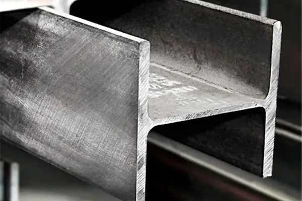
H beams, I beams, U channels, and angle steel are widely used in industrial buildings, platforms, equipment supports, and structural frames. Their performance depends not only on the strength of individual members but also on the accuracy and quality of their connections. Misaligned bolt holes, uneven bearing surfaces, excessive gaps, weld defects, and installation deviations can delay fabrication and erection. Many of these problems can be avoided through accurate drawings, dimensional checks, controlled fabrication, and inspection before assembly.

1. Understand the Connection Requirements of Each Profile

Different structural steel profiles create different connection conditions. 

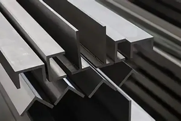
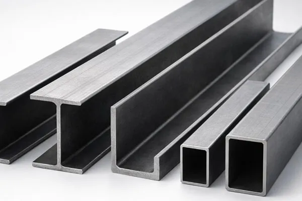
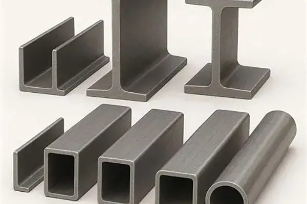
  • H beams and I beams: Commonly used as beams and columns. Connections may involve end plates, cleats, bolts or welded joints. Web and flange positions must match the approved connection details. 
  • U channels: Often used for secondary supports, framing and edge members. Their open-section geometry makes channel orientation and connection access important.
  • Angle steel: Frequently used in bracing, brackets and support assemblies. Confirm whether the design requires single-leg or double-leg connections and check the installation orientation.

For all profiles, connection suitability depends on the structural design, applied loads and service conditions. Nominal section dimensions alone cannot determine whether a connection is adequate.

2. Check Drawings and Dimensions Before Fabrication

A mismatch between structural drawings, fabrication drawings and supplied materials is a common source of fit-up problems. Before cutting, drilling or welding, confirm:
  • Profile designation, steel grade and section orientation
  • Member length, straightness and twist
  • End squareness and cutting accuracy
  • Bolt-hole positions, diameters and spacing
  • Connection plate dimensions and thickness
  • Weld locations, joint preparation and specified details
  • Applicable fabrication and erection tolerances
Compare actual material dimensions with the relevant product standard and purchase specification. Fabrication dimensions and connection tolerances should be checked against the approved drawings. Do not enlarge holes, force members into position or modify load-bearing components simply to make an assembly fit. Any change affecting the connection should be reviewed and approved by the responsible engineer.

3. Reduce Problems in Bolted Connections

Bolted connections require accurate hole positioning, compatible fasteners and correct installation procedures. Before assembly, verify bolt grade, diameter, length, nuts and washers against the design. Check that holes are correctly located and free from burrs or obstructions. Also distinguish between bearing-type and slip-critical connections. Slip-critical connections require particular attention to faying-surface condition and the specified installation procedure. During installation:
  • Align components without forcing them into position.
  • Keep mating surfaces in the condition required by the design.
  • Use the specified bolts, nuts and washers.
  • Follow the approved tightening method and sequence.
  • Complete and record inspections where required.

For pretensioned high-strength bolts, follow the applicable installation and verification requirements. Visual inspection alone cannot confirm the required bolt pretension.


4. Control Welding and Fit-Up

Welded connections require suitable joint preparation, accurate fit-up and controlled welding procedures. Before welding, confirm the material grade, joint design, root gap, alignment and surface cleanliness. Welding consumables and parameters should follow the approved Welding Procedure Specification (WPS). Where required by the project, verify welder qualifications and applicable welding procedure qualifications. Excessive restraint, unsuitable welding sequences and uncontrolled heat input can contribute to distortion. Fabricators should plan tack welding, final welding and dimensional checks in a suitable sequence. Weld inspection may include visual testing and additional non-destructive testing (NDT), depending on the project specification and approved inspection plan. The testing method and acceptance criteria should not be assumed to be the same for every structural weld.

5. Check Alignment During Installation

Connection problems may become apparent during site erection, even when individual components have passed fabrication inspection. Before completing connections, check:
  • Correct member identification and orientation
  • Support and bearing conditions
  • Bolt-hole and connection plate alignment
  • Member level, plumb and position
  • Compliance with specified erection tolerances
  • Completion of required bolting and welding inspections
Temporary bracing and erection sequences should follow the approved construction method. Unplanned site modifications may change structural load paths and should not be treated as routine adjustments.

6. Investigate Recurring Connection Problems

If a connection repeatedly develops loose bolts, cracks, corrosion or deformation, inspect the entire assembly rather than simply replacing the visible damaged component. Possible contributing factors include:
  • Loose bolts: Incorrect installation, vibration or connection-related issues.
  • Weld cracking: Material condition, welding procedure, restraint, stress or fatigue.
  • Corrosion: Exposure conditions, coating damage, water accumulation or poor drainage.
  • Deformation: Applied loads, inadequate support or deviations from design assumptions.
These symptoms do not establish the root cause by themselves. Cracks and significant deformation should be assessed by a qualified structural engineer. Repairs or modifications should follow an approved engineering procedure.

FAQ

Q1. Why do H beam connections sometimes fail to align?
A1: Common causes include incorrect measurements, fabrication errors, member deformation, drawing discrepancies and deviations from specified erection tolerances.

Q2. Can bolt holes be enlarged on site?
A2: Not without approval. Hole modifications may affect connection performance and must follow an engineered modification or repair procedure.

Q3. Is welding always better than bolting for structural steel profiles?
A3: No. The choice depends on structural design, fabrication facilities, installation access, inspection requirements and future maintenance considerations.

Q4. What should be checked before welding structural steel profiles?
A4: Confirm material identification, joint preparation, alignment, root gap, approved WPS, welding consumables and personnel qualifications where required.

Q5. What should be done if cracks appear around a structural connection?
A5: Arrange an engineering assessment and follow the applicable safety procedures. Do not cover, grind or repaint a crack before its extent and cause have been evaluated.

Conclusion

Reliable structural steel connections start with accurate specifications and continue through fabrication, welding, bolting and site installation. Checking dimensions, following approved connection details and investigating defects before assembly can reduce avoidable rework and installation delays. For projects involving H beams, I beams, U channels and angle steel, connection requirements should always be coordinated with the structural design, applicable standards and approved fabrication documents.

  • Prev : How to Inspect Structural Steel Profiles Before Delivery
  • Next : No matching information found
  • Tags : structural steel profile connection problems , H beam connections , steel channel connections , angle steel bracing , structural steel bolted joints , steel profile welding

Latest news list

  • structural steel profile inspection,H beam inspection; I beam dimensional tolerance; U channel quality control; angle steel inspection
    Structural steel profiles are widely used in industrial buildings,bridges,equipment supports and other load-bearing structures,Before delivery,their dimensions,material properties and surface condition should be checked against the purchase order and applicable product standards,For H beams,I beams,U channels and angle steel,inspection should cover more than a visual check,The following points provide a practical guide for buyers,project engineers and quality teams preparing structural steel profiles for dispatch,
  • structural steel profile corrosion protection,outdoor steel profile corrosion,H-beam rust prevention,angle steel corrosion,galvanized structural steel
    H beams,I beams,U channels,and angle steel are widely used in outdoor structures,including equipment platforms,pipe supports,access walkways,storage facilities,and industrial frames,Once installed,these profiles are exposed to rain,humidity,airborne pollutants and,in some locations,salt or chemical contamination,Corrosion does not develop evenly across every steel member,Water can collect around connections,beneath base plates or inside poorly drained details,If the protective system does not match the service environment,corrosion may gradually reduce the effective steel section and increase maintenance costs,Effective corrosion protection starts with understanding the exposure conditions,selecting a suitable protective system,and addressing details that allow moisture to accumulate,
  • structural steel profile production,H beam production,I beam production,U channel production,angle steel production,structural steel profile inspection
    Structural steel profiles are widely used in industrial buildings,bridges,infrastructure,equipment frames and other construction projects,H beams,I beams,U channels and angle steel have different cross-sectional shapes,each designed for particular structural and fabrication requirements,Although these products look different,their manufacturing processes share several stages,including steel preparation,forming,cooling,straightening and inspection,Understanding how structural steel profiles are produced helps engineers and buyers evaluate product specifications and communicate more effectively with suppliers,
  • FBE coated steel pipe inspection and maintenance,FBE pipeline maintenance,steel pipe coating inspection,FBE coating defects
    FBE (fusion-bonded epoxy) coating provides external corrosion protection for steel pipelines,particularly in buried and submerged applications,However,the coating does not eliminate the need for inspection after installation,Construction damage,field joint defects,ground movement and third-party excavation can affect the protective system during pipeline service,For buried pipelines,most of the external coating cannot be examined directly without excavation,Operators therefore need a planned integrity management approach that combines construction records,accessible-area inspections,corrosion monitoring and targeted investigation of suspected defects,
  • FBE steel pipe export supply,FBE steel pipe export,FBE pipe shipment,international steel pipe supplier
    Exporting FBE coated steel pipes for an overseas pipeline project involves more than arranging production and booking shipment,The order must move through several connected stages,from technical specification review and pipe sourcing to coating coordination,inspection,documentation and delivery,Each stage needs to follow the approved purchase requirements,A mismatch in pipe specifications,coating details,inspection records or shipping documents can delay acceptance and affect the project schedule,A clear coordination process helps buyers maintain control over these details before the goods leave the country of origin,

Find what you need ?

close
We use cookies and other tracking technologies to improve your browsing experience on our website, to show you personalized content and targeted ads, to analyze our website traffic, and to understand where our visitors are coming from.